Structural simulation in design
The aims of this analysis are to determine how much hydrostatic pressure the hull of a deep-sea submarine can sustain and to establish the depths to which it could safely venture. In so doing, we will attempt to elucidate why the OceanGate Titan submarine imploded and shed light on the mechanisms that brought about its destruction.
Our approach was as follows: A simplified CAD model is created and discretized to obtain a finite element model (FEM). Orthotropic nonlinear material properties are used to represent the composite hull, and isotropic nonlinear properties are used for the titanium components. Nastran multi-step nonlinear solver (Solution 402) is used to conduct the analysis in Simcenter 3D. This solver can capture the nonlinearities and the dynamic aspect of the event, such as large displacements, plasticity, buckling, and fast deformation.
The analysis results show the spread of plasticity and damage throughout the structure as the exterior pressure increases.
This study illustrates the importance and usefulness of structural simulations in designing safe and reliable products.
CAD model of submarine
First, a simplified CAD model of the submarine is created in Siemens NX based on publicly available data. The model consists of a pressure vessel, landing frame and an aft fairing. The complete CAD model is shown below.
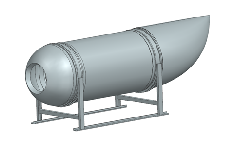
Figure 1: Submarine CAD model
Pressure vessel sub-assembly
The main point of interest of the analysis is the hull of the submarine, of which an exploded view is shown in figure 2. This sub-assembly comprises a carbon-fiber cylindrical hull to which two titanium rings are bonded at either end. Titanium endcaps are then bolted onto these rings to complete the pressurized enclosure of the submarine, with the fore end cap having an opening for a viewport. In addition, the landing frame is made of steel beams.
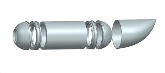
Figure 2: Exploded view of pressure vessel and aft fairing
Finite element model
Each component of the submarine is meshed to generate individual FEMs, which are combined in an assembly FEM. A large element size is used to decrease the computation time of the nonlinear analysis. The pressure vessel components are meshed with 3D elements, while the aft fairing and the landing frame are meshed with 2D thin shell elements. The model has roughly 32,000 nodes.
Ideal connections between the components are defined with surface-to-surface gluing. The glue connections are automatically created by Simcenter 3D, which can detect the face pairs within a search distance.
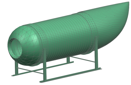
Figure 3: Assembly FEM of the submarine
Material properties
Titanium
A bilinear stress-strain curve is defined in Simcenter 3D for the titanium components. The bilinear curve is a valid approximation since the stiffness of the titanium is almost linear once it reaches plasticity.
Carbon Fiber
The cylindrical carbon fiber hull’s manufacturing process is filament winding, which consists of winding epoxy dipped carbon fibers around a cylinder. It is assumed that the filaments’ angle is tangential to the cylindrical theta direction.
To model the carbon fibers, we explored three options:
- Modelling the composite layup using Simcenter 3D Laminate module. This option allows to compute plies and interlaminate failure index.
- Creating a micro-scale model with damage laws using Simcenter 3D MultiMech module. This option allows to compute damage at the micro-scale level and couple the micro-scale properties with the FEM properties.
- Using an orthotropic material with stress-strain law. This simplification allows to define nonlinear material properties in three directions.
The third option is used in the analysis. An orthotropic material is defined, with a master stress-strain curve defined for the fiber direction and Hill stress ratios modifying this master curve for the transverse and thickness directions. Even though a carbon fiber composite is not a ductile material, this approach allows to have a reduction in the stiffness of the carbon fiber once it reaches its tensile stress limit in any direction. It is also a good assumption to represent the stiffness of the hull accurately.
The direction of the fiber is shown by the yellow arrows in Figure 4.
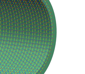
Figure 4: Orientation of the carbon fibers
The material properties of carbon fiber and titanium are compiled in table 1.
Table 1: Material properties
| Material | Direction | Young’s Modulus (MPa) | Elastic / Tensile Limit (MPa) | Shear Strength
(MPa) |
| Carbon Fiber | Longitudinal | 140000 | 1000 | 50 |
| Transverse | 10000 | 100 | – | |
| Titanium | – | 105000 | 210 | – |
Analysis setup
To capture the nonlinearity of the event, a Nastran nonlinear solution (Solution 402) is performed. The solution contains two steps, a Nonlinear Static subcase followed by a Nonlinear Dynamic subcase. The difference between these two types of subcases is the inclusion of inertia effect: the static subcase does not take into account inertia whereas the dynamic subcase does. Therefore, a static subcase is computationally lighter but is limited to quasi-static events. For high-speed events, such as implosions in a high-pressure environment, a dynamic subcase is required.
The boundary conditions are:
- Constraint: Bottom of the landing gear is fixed. This constraint is applied for stability purpose as the submarine is in a free-free environment.
- Load: A pressure load is applied to the carbon fiber hull and end rings. The pressure increases linearly.
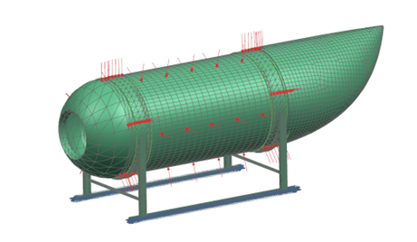
Figure 5: Submarine loads and constraints
To determine the beginning of the implosion instability, a preliminary nonlinear static solution is performed with a load increasing linearly from 0 to 100 MPa in a fictious time of 100s. This solution failed to converge after 62s, due to the instability of the implosion phenomenon. This preliminary result indicates that the implosion is likely to happen at around 62 MPa.
The second analysis consists in a nonlinear static subcase that reaches a final pressure of 62 MPa followed by a nonlinear dynamic subcase with the load increasing gradually to a pressure of 63 MPa. The nonlinear dynamic subcase has time step of 10-5 seconds in order to capture the rapid implosion phenomenon.
Results
The aim of this analysis is to determine the maximum depth that this deep-sea vehicle can sustain before having damage or failure. The implosion pressure determined by the analysis is 62.5 MPa, which corresponds to a depth of 6,250 meters. Many assumptions and simplifications were made in this analysis, but this result provides a valid approximation of the maximum depth the OceanGate Titan could have reached.
Considering that, why would this submarine fail when exploring the wreck of the Titanic, which is only 3,800 meters deep? Other factors come into play before the ultimate failure of the vehicle. The animation below shows the plastification of the pressure vessel components.
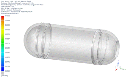
Figure 6: Spread of plastification.
Since carbon fiber is not ductile, the “plastic strain” experienced by a carbon fiber element in the simulation would instead consist of damage in real life. Figure 7 is a graph of the plastic strain in the titanium in one of the end rings (blue curve) and in the carbon fiber on the edge of the hull (red curve).
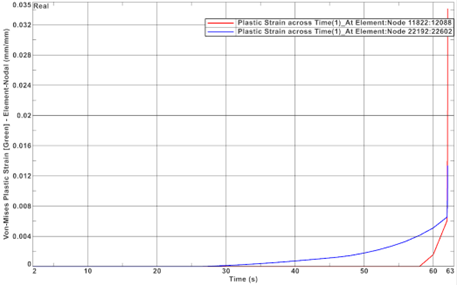
Figure 7: Number of plastified elements versus time
The animation and figure 7 show that as the submarine goes deeper, the titanium components begin to yield at a pressure of around 30 MPa or a depth of 3,000 m. As the pressure continues to increase, the titanium yields to a point where its rigidity is less than the carbon’s rigidity. The pressure is then mainly supported by the carbon fiber hull at around 5,600m. At this pressure, damage begins to occur in the hull and ultimate failure happens once the submarine reaches a depth of 6,250 meters.
Figure 8 is a schematic of the displacement of a node on the edge of the hull versus pressure. Note that the slopes of the curve are exaggerated to emphasize the stages of titanium yielding, carbon fiber damage and implosion.
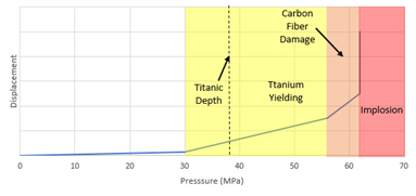
Figure 8: Displacement a node on the hull vs pressure
From figure 8, we see that from 0 to 30 MPa the structure is in an elastic, linear state. The displacements are small and fully reversible. Larger displacement begins once the titanium starts to yield at 30 MPa. The structure is now in a non-linear state; if the load is removed, residual displacements would remain. At 56 MPa, damage start to occur in the carbon fiber, which increases the displacement slope. At 62.5 MPa, the slope becomes vertical as the implosion occurs almost instantly.
The shaded regions’ colors in figure 8 indicate the risk associated with operating the submarine in these conditions. 30 to 56 MPa is the titanium yielding region, 56 to 62.5 MPa is the carbon damage region and 62.5+ MPa is the implosion region.
The final deformation after the implosion depends on where the hull failed first. The non-linear analysis predicts that the initiation of the implosion would come from the connection between the hull and the titanium end rings. An exaggerated shape is shown in Figure 9.
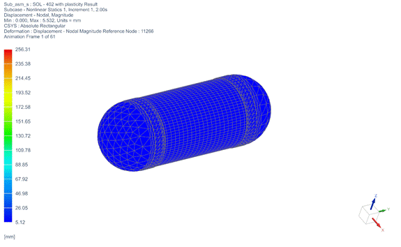
Figure 9. Deformation at the beginning of the implosion
The implosion region should obviously never be reached. The carbon fiber damage region should not be reached, either, since the effect of the damage is hard to assess and failure might happen earlier in this region. The titanium yielding region is not a region where catastrophic failure is expected. However, repeated loading over yield creates risks of low-cycle fatigue. This could result in cracks initiation or titanium failure. Each time the submarine reaches this depth, more load could be transferred on the carbon fiber hull. This repeated loading, combined with potential manufacturing defects, means that the carbon fiber could be damaged, and rupture could occur at pressures well below the values 62.5 MPa.
To provide a maximum operating depth, safety factors must be determined. Given the risks associated with a deep-sea dive and the assumption and simplifications made in this analysis, two safety factors are chosen.
- A safety factor of 4 is used for ultimate failure of the submarine (implosion).
- With this safety factor, the pressure should not be greater than
, which corresponds to a depth of 1,560m.
- With this safety factor, the pressure should not be greater than
- A safety factor of 2 is used on the Yield allowable (plastification).
- With this safety factor, the pressure should not be greater than
, which corresponds to a depth of 1,500m.
- With this safety factor, the pressure should not be greater than
Therefore, the submarine analyzed should not exceed a depth of 1,500 meters.
Conclusion
In conclusion, this analysis illustrates the wealth of information that can be obtained through simulation and its importance in developing a product that is safe, durable, and reliable. The need for simulation is augmented in applications, such as this deep-sea submarine, where manufacturing and testing is extremely costly and time consuming.
Although this analysis could have been partially done in linear analysis, Nastran nonlinear solution allowed us to understand the mechanisms that led to the implosion of OceanGate Titan.
Interested in what simulation can do for your product safety and quality?
Contact a Maya HTT expert today to explore simulation solutions.