Comparing the results of three different 2.5 axis operations
CAM programmers are tasked with finding the best manufacturing method for the specific part they are to manufacture. Often, multiple operations can accomplish the same task. In this paper, we compare three different operations and their objective impacts on the process.
Although the analysis was done on 2.5 axis operations, these strategies can also be used for multi-axis machining. The potential combinations of parts, cutting tools and process parameters are nearly unlimited.
 Experiment setup
 Experiment setup
We will take a closer look at two newer strategies, 3D Adaptive and Quick Roughing, and compare them to the legacy cavity milling approach.
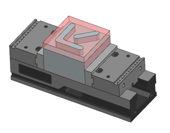
The part
The part used for comparison was a 6” by 6” block with a 3/4” deep profile.
A relatively simple geometry was chosen to allow easier comparison between different tool paths. This geometry provides both concave and convex corners.
The assumed material for this part is grade 5 titanium (Ti-6Al-4V).
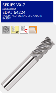
The tool
We chose to simulate using a ½” endmill from GARR’s VX-7 series and cutting parameters recommended by GARR. We wish to reference the published speeds and feeds table to ensure analysis is done using realistic cutting conditions.
 Cutting parameters
 Cutting parameters
- Speed
- 200 SFM
- Engagement:
- Axial .750
- Radial 15%
- Chip Load:
- 0025
- Feed
- .035 ipt
Due to the relatively small radial engagement, it is necessary to correct the feed rate to achieve the desired chip load.
 Analysis method
 Analysis method
 Analysis was done using NPRO within NX. The data was exported and brought into Excel to facilitate the direct comparison between tool paths. Cycle times are determined using NX default values and should provide a representative comparison.
NPRO can optimize operations around user-defined objectives including power, feed force and chip thickness. In this analysis, we did not optimize the tool paths but simply used the analysis tools to understand and compare.
Comparison
We will be comparing tool bending force on the XY plane as well as actual predicted chip load.
Key assumptions:
- Spindle torque and power are known to be sufficient.
- The process is stable (no chatter).
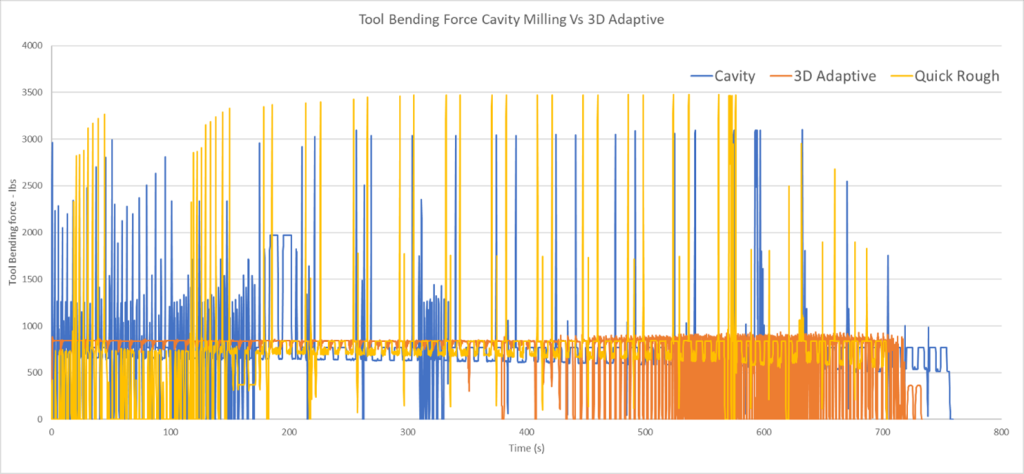
Tool bending force
Tool bending force can also be thought of as “feed force” — the force required to push the cutter through the cut. Feed force is an important consideration, as it is the primary force contributing to deflection.
In an ideal world, the feed force should be perfectly constant. Force spikes tend to cause issues with parts slipping in work holding or spontaneous tool failure. Mean force has a significant impact on cycle time.
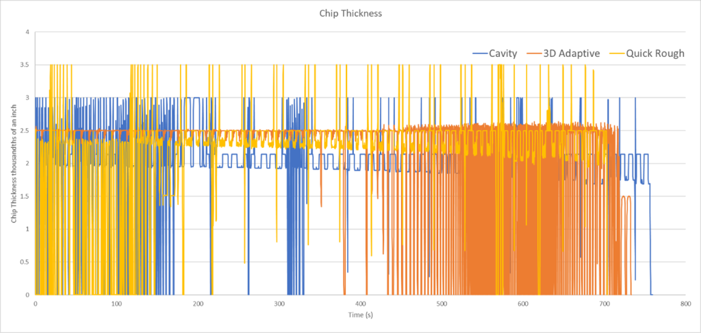
Chip thickness
There are a couple of hard limits when it comes to chip load. Regardless of power and force limitations, we must ensure there is sufficient room in the flute to allow the chip to evacuate.
For all three processes, the feed per tooth in NX was set to 0.0035. The desired chip load is 0.0025 (15% axial engagement). It is interesting to note the difference between the various approaches:
- Cavity mill seems to average 0.0025 chip thickness, occasionally spiking to .003.
- 3D adaptive is doing an excellent job of not exceeding the desired chip load.
- Quick Rough routinely spikes the chip load to 0.0035.
Conclusion
Overall, the 3D adaptive approach demonstrated a significant advantage in terms of process stability. For this reason, we expect the operation to provide the most efficient manufacturing strategy with the most room for optimization. The well-constrained feed force and chip thickness should lead to increased tool and spindle life.
The process stability of Quick Rough was slightly worse than cavity milling but provided fast and easy tool path generation. It is particularly well suited for one-off parts where programming time is critical for profitability.
Summary of results
| Method | Cavity | 3D Adaptive | Quick Roughing |
| Summary
|
Legacy tool path used as baseline for all other comparisons. | Introduced with NX2306 optimizes to provide smooth cutting conditions.
· Chip thickness is strictly adhered to. · Force spikes are very minimal. · Generally, can use more aggressive cutting parameters without sacrificing process stability. |
New tool path as of 2312.
· Quick rough makes efficient use of computational resources to rapidly create tools paths. · Particularly advantageous for the generation of long programs. |
Interested in exploring the best approach for your manufacturing needs?
Contact a Maya HTT expert today
Discover services to improve productivity on the shop floor