 Printed circuit boards (PCBs) present a difficult structural dynamics problem. A PCB carries components with different masses on a comparatively thin substrate. That delicate board has to cope with concentrated, uneven loads on connectors and mounting points.
When under vibration, there’s often relative motion between components and the PCB due to local board deflection, too — and the motion fatigues component leads and solder joints. We can see this in testing from NASA, which has documented the connection between PCB vibration response and fatigue life. The IPC, meanwhile, includes random vibration among the qualification methods used to evaluate solder-joint reliability.
The long and short of it is that vibration is a challenge for PCBs and the structural engineers who design them. Here are seven specific obstacles to overcome, and how to obtain useful answers quickly enough to influence the design.
1. PCB Assemblies are Sensitive to Local Vibration Response
Components in the PCB alter local mass distribution. If there’s any mounting stiffness, it can affect board response. A resonance might, for example, produce significant strain around a component even when the external housing remains within acceptable limits.
Per the same NASA research above, out-of-plane bending is a major contributor to local displacement between the board and mounted components, and causes fatigue in electrical leads.
Your vibration analysis, therefore, must have enough model detail to resolve board behavior and component-level structural response.
2. Qualification Often Requires Multiple Random & Sine Cases
Any electronics intended for aerospace environments will face substantial vibration qualification requirements.
NASA guidance calls for component-level random vibration testing along three mutually perpendicular axes. It’s common for qualification programs to use sine or periodic vibration when necessary in an expected mission environment.
Each axis has its own response case. The more additional qualification levels there are, though, the more work there is to do. If there are any design changes, engineers will also have to revisit those analyses.
All told, it’s a heavy analysis workload when one electronics assembly contains several boards or when multiple mounting configurations require evaluation.
3. Spectral-Line Selection Will Need Extra Setup
An effective random vibration analysis must have sufficient frequency resolution around structural resonances.
With too few integration frequencies, there’s a risk of poor resolution of narrow response peaks. On the other hand, excessive frequency resolution will increase processing time. What’s an engineer to do?
If you’re using a conventional workflow, this is a tradeoff you’ll have to decide before each solve. Spectral-line selection is already a lengthy analysis process, but the technical decisions are thus even tougher with large models with numerous modes.
4. Large OP2 Files Slow Post-Processing
Detailed electronics models produce large result files. A Nastran model may include extensive element outputs across several vibration cases. In that scenario, you could easily generate an OP2 file that’s too slow and cumbersome for a general graphical post-processor. It takes time to load the file, and even more to extract relevant quantities.
So, reduce the model, right? If you’re reducing the model purely to keep post-processing manageable, you’re also removing detail that engineers originally included for a reason.
Structural analysis software has to support the model fidelity required by the engineering problem. Result handling can’t be the limiting factor.
5. Complexities with Peak Stress, Fatigue and Modal Results
There are a few structural responses needed for vibration qualification:
- Peak stress identifies highly loaded regions.
- Fatigue calculations assess cumulative damage under repeated excitation. Modal results explain which structural modes dominate the response.
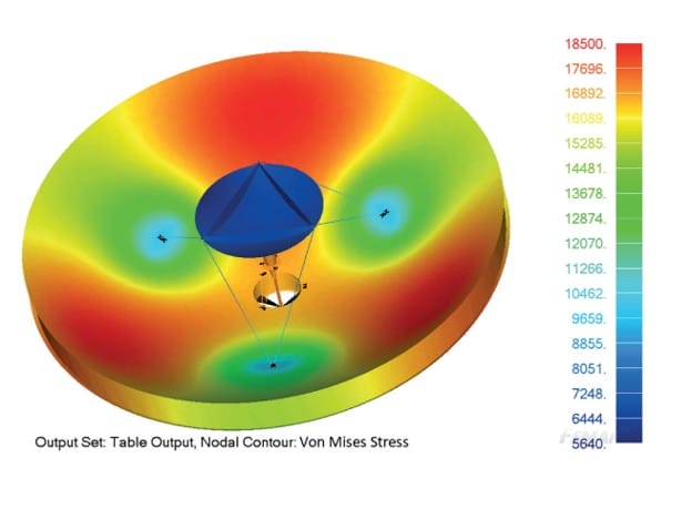
There can be more statistical complexities, such as derived quantities. Von Mises stress does not follow the same Gaussian behavior as individual stress components in random vibration analysis. If you treat every output as a simple RMS result, there’s a high risk of inaccurate peak estimates.
With all these complexities, structural engineers need fast response processing that can handle those quantities correctly and present them in a form suitable for design review.
6. Long Analysis Cycles Consume Engineering Hours
High solver times are part of the cost of vibration analysis, but engineers also spend time preparing frequency inputs and managing output requests. They may need to inspect very large result sets afterward, and repeat qualification cases for additional axes.
Those hours spent waiting on each cycle ultimately reduce structural analysis throughput for the project. In instances where several engineers may share the same qualification schedule or compute resources, it’s an even more visible bottleneck.
7. Slow Results Limit Design Exploration
What if a structural engineer wants to compare a thicker PCB against an added stiffener, or examine mounting locations or component placement?
It takes swifter random and sine vibration analysis cycles to remove the limitations on that exploration.
With a slow analysis, there are fewer opportunities to iterate and find a lighter design or reduce peak response before the project gets to hardware testing. The number of technically worthwhile scenarios could potentially be huge, but it’s the project schedule that determines how much analysis gets completed.
Accelerate Electronics Vibration Analysis With SATK
The Structural Analysis Toolkit (SATK) from Maya HTT extends your existing Simcenter Nastran or MSC Nastran workflow with specialized vibration post-processing.
The parallelized random processor of the SATK reads SOL 103 normal-mode results and performs random base-excitation response calculations. With hybrid integration, there’s no burden on analysts to manually select integration frequencies. The SATK also:
- Handles random vibration and sine vibration
- Calculates peak derived stresses and strains
- Supports fatigue analysis for random vibration, sine dwell and sine sweep
- Processes large OP2 files quickly, so engineers don’t have to simplify the model for post-processing
Achieve random vibration processing up to 200× faster than comparable software with the convenient and powerful SATK, which runs on Windows and Linux and also supports batch execution.
The SATK from Maya HTT accelerates analysis for your electronics team so you have more room for additional design studies in the qualification schedule. Speak with an expert to keep the Nastran workflow you already use and spend fewer hours waiting for response results.
Frequently asked questions
What Is Vibration Analysis in PCB Design?
Vibration analysis predicts how a printed circuit board and its mounted components respond to dynamic excitation. Engineers examine board deformation plus modal response to identify locations susceptible to high stress or fatigue.
Why Are PCBs Vulnerable to Vibration?
PCB flexure creates relative displacement between the board and mounted components. Repeated motion places cyclic loads on component leads and solder joints.
What Is Random Vibration Analysis?
Random vibration analysis evaluates structural response to broadband excitation described by a power spectral density, or PSD. It is widely used to represent environments such as launch vibration.
How Is Sine Vibration Different From Random Vibration?
Sine vibration applies harmonic excitation at defined frequencies. Random vibration distributes excitation energy across a frequency spectrum.
Why Do Large OP2 Files Create Problems?
Detailed finite element models produce substantial quantities of nodal and elemental results. Large OP2 files increase loading and post-processing time in general-purpose graphical tools.
Does SATK Replace Nastran?
SATK works with Simcenter Nastran and MSC Nastran results. Its processors extend the existing Nastran workflow with specialized vibration analysis and post-processing capabilities.
Does SATK Support PCB Fatigue Analysis?
Yes. SATK supports fatigue calculations for random vibration as well as sine dwell and sine sweep excitation.
How Does SATK Speed Up Random Vibration Analysis?
SATK uses a parallelized random processor and hybrid integration. Maya HTT reports performance up to 200× faster than comparable software while maintaining engineering accuracy.