The McGill Formula Electric (MFE) team designs, manufactures, and races a formula style electric vehicle every year. In the first part of this blog post series, a system simulation of the cooling of the vehicle was built in Simcenter Amesim. In part two, the performance of the individual cooling devices was investigated further in CFD with Simcenter Star-CCM+.
In this third installment, the data obtained from CFD will be directly used to replace Simcenter Amesim components and increase the accuracy of the system simulation.
Reduced order model of the cooling devices
While Simcenter Star-CCM+ and Simcenter Amesim can be directly coupled, the preferred approach here is to use reduced order models (ROMs). The creation of ROMs has two main steps: a performance sweep in Simcenter Star-CCM+ and model training and export in Simcenter Amesim.
CFD sweep of the cooling devices
The first question to answer before making the ROM of the CFD simulation is: will the model be based on steady-state data or time-series data. The preferred approach here is to create the model based on steady-state data from a performance sweep of the steady-state CFD simulation. The transient behavior of the cooling device can be accounted for by introducing a first-order lag with the time constant corresponding to the thermal time constant of the device.
Before proceeding with this technique, a validation study was performed to check what parameters influence the thermal time response.
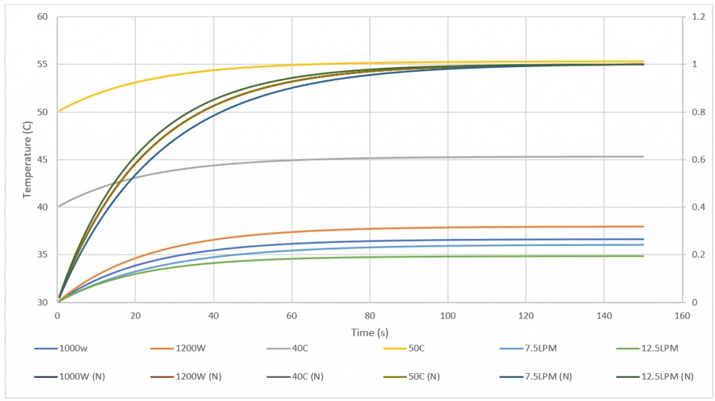
Figure 1: Motor temperature response for a step input in heat rejection, ‘’N’’ stands for normalized
The study was set up using the design manager tool built into Simcenter Star-CCM+. The heat rejection, motor initial temperature, and coolant flow rate were individually varied with respect to a baseline. It was concluded that the only parameter that has an impact on the thermal time constant is the coolant flow rate. This can be seen with the normalized curves all overlapping except when the coolant flow rate was varied. The approach selected is, therefore, valid as long as the thermal time constant is adjusted when the coolant flow rate is varied.
The next step in the analysis is to create a second design manager project in Simcenter Star-CCM+. This one will use the steady-state simulation of the cooling jacket, which will make it possible to rapidly sweep through multiple boundary conditions. The parameters varied were the inlet coolant temperature, the coolant mass flow rate, and the motor heat rejection. The responses monitored were the motor average temperature, the increase in coolant temperature, and the pressure drop. They can be visualized below.
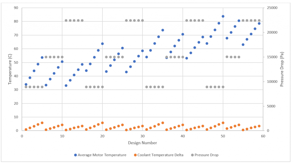
Figure 2: Responses monitored to create ROM
Reduced order model creation
The next step is to take the sweep data and import it into the Simcenter Amesim ROM Builder. This tool is fully integrated into Simcenter Amesim. It allows us to create a custom Simcenter Amesim block from the training data and use it right away in a simulation.
With the ROM builder, we can create models for static data, time-series data, state-space data, and frequency-response data. The preferred approach is to use static data from the CFD sweep and to introduce a first-order lag with the thermal time constant.
The CFD sweep data was split randomly in training and validation data and fed into the ROM builder. We can then create the ROM using either a neural network, a response surface, or a Gaussian process. All three were tested and compared. It turned out that the thermal response was quite simple to model and that all models yielded very good training and validation fidelity.
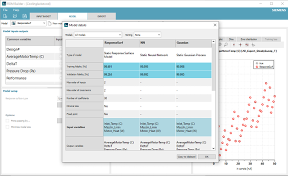
Figure 3: ROM builder and model comparison in Simcenter Amesim
The Gaussian process was selected, and the model was exported as a Simcenter Amesim component. A quick benchmarking simulation was made in Simcenter Amesim and Simcenter Star-CCM+ to ensure that the ROM was achieving its purpose of accurately capturing the transient response observed in CFD at a fraction of the computational cost.
The ROM does require a significant resource investment to sweep through the boundary conditions, but once the data is fitted to the model, what would take four hours to run in Simcenter Star-CCM+ takes only a few seconds on the same workstation in Simcenter Amesim. The accuracy of the ROM is also quite good and has only a slight offset from the transient CFD simulation.
Figure 4: Transient simulation with stepwise random heat generation
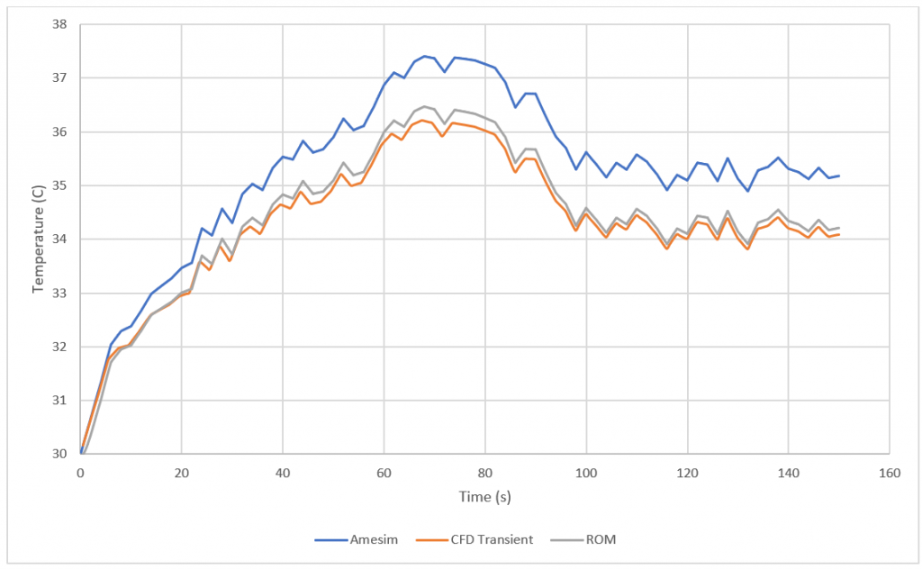
Figure 5: Average cooling jacket temperature response to random stepwise signal
The exact same steps were followed to create an ROM corresponding to the cold plate. In addition, the cold plate’s ROM allows us to monitor the maximum temperature of the device in Simcenter Amesim.
Simcenter Amesim model 2.0
The ROMs replaced the original Simcenter Amesim components in the cooling system simulation. The simulation now more accurately depicts the behavior of the cooling system components, and does so much faster than CFD.
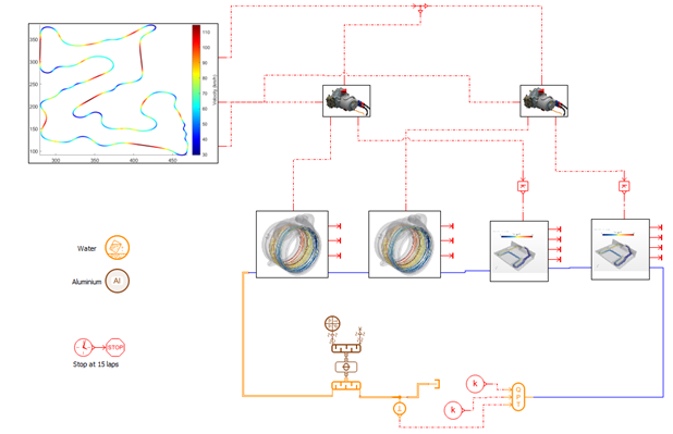
Figure 6: Liquid cooling loop with super components containing the ROMs
Each of the super components contains the ROM, and a means to change the coolant flow conditions based on the cooling device performance and the heat absorption. The temperature signals go through a first-order lag block to account for the time dependency.
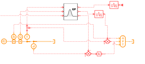
Figure 7: Super component content to include the ROM
Next steps and physical testing
The simulation has evolved from that of a basic system to one that leverages CFD and ROMs, but there is still room for improvement. For instance, Simcenter Amesim offers other ways of modeling the radiator, such as with embedded CFD, the Heat Exchanger Assembly Tool (HEAT), or the dedicated cooling system library. While these might be investigated, the clear next step for this project is validation.
Performance characteristics such as the coolant temperature increase, the temperature at specific points, and the thermal time constant will be obtained by running the motor/inverter coupled to a dynamometer. The full model will also be validated in a track environment by using the torque/RPM traces as well as the ambient conditions to run the model and compare the predicted temperatures to the actual ones.
The performance of the radiator will also be measured on a test bench using a small-scale 3D-printed wind tunnel to sweep through coolant inlet temperature as well as air and coolant mass flow rate.
All these tests will allow us to validate the work that has been done in Simcenter Amesim and Simcenter Star-CCM+, and they will also serve to tune the models.
Series conclusion
The goal of this series was to showcase how to develop and leverage the digital twin of an electric vehicle cooling loop to make design decisions. This was achieved using Simcenter Amesim and Simcenter Star-CCM+ in a complementary and collaborative manner.
The outcome is a model that captures the transient behavior of the full loop under different conditions and for different designs. As outlined above, a significant part of the project remains to be completed with validation and physical testing.