Heat exchanger data:
Heat rejected from fluid to heat exchanger = 96KW
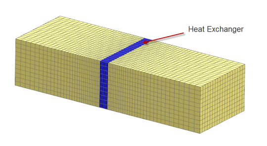
Cross sectional area in model = 1.946 m2
The Thickness (L) of the heat exchanger in the model is 0.214 m
The following was obtained from the manufacturer of the heat exchanger:
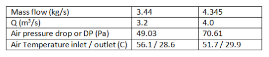
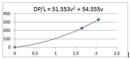
From the above information the following data points are obtained:
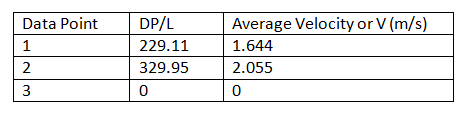
The previous data is plotted to obtain DP/L vs V and fitted with a 2nd order polynomial
An Isotropic blockage is prescribed to the heat exchanger air volume using the Head Loss and Permeability method.
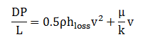
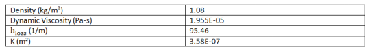
The values for h_loss and k can be obtained from the above equation and curve fit. Using data for air at 50C, the following was obtained.
The previous values for head loss and permeability are entered in the flow blockage dialog box. A heat load is applied to the heat exchanger air volume using a value of -95kW.
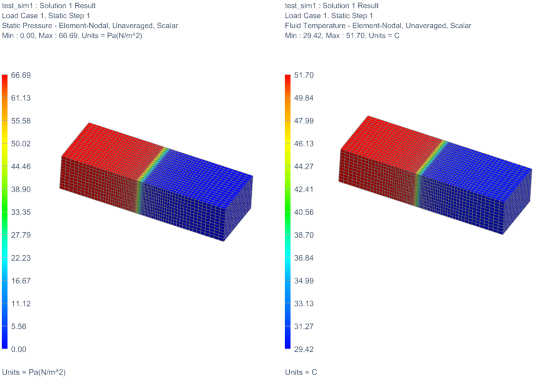
Testing Results:
Case 1: mass flow = 3.44 kg/s

Case 2: mass flow = 4.345 kg/s