Quick Overview
NX Advanced Simulation provides several methods to define the thickness of 2D elements, such as derived from a mid-surface, assigned through Element Associated Data or from a physical property table. It is helpful to validate the thickness definition prior to solving your model.
This Tips & Trick shows how to display a fem’s 2D element thickness values. In addition, NX lets you create a field of 2D element thicknesses, which you can reuse in the same or different model, on finer or different meshes altogether.
Steps
1. Display 2D element thickness
NX offers three different types of display to view and validate the distribution of 2D element thickness in your model.
1.1 Thickness Contour
To create a contour plot of 2D elements thickness, in the sim navigator right click on a Mesh collector or an individual mesh and select Plot Thickness Contours.
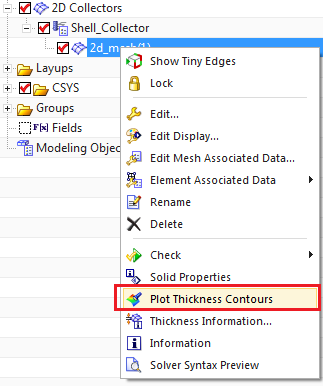
Figure 1. Plot Thickness Contours.
Thickness values are displayed as element-nodal scalar results. When you generate a thickness plot, the Post Processing toolbar is enabled, and you can use post-processing tools to view and interrogate element thicknesses. For example, you can use Edit Post View to modify the thickness display, and you can use Identify Results to probe thickness values at nodes and write thickness information to a spreadsheet or comma-separated-value file.

Figure 2. Thickness values are displayed as element-nodal scalar results.
1.2 Hedgehog display
In a hedgehog display, NX uses both colors and the relative length of lines (drawn at the centroid of each element) to indicate the variance in thickness values across the mesh. This type of thickness display is temporary and is cleared when you refresh your graphics window.
To create a hedgehog display, in the sim navigator right click on a Mesh and select Thickness Information.

Figure 3. Thickness Information commands.

Figure 4. A hedgehog display of 2D element thickness.
1.3 Display 2D Element Thickness
NX graphics can display the 2D elements such that they appear to have thickness, like solid elements. Offsets are shown as well. To create such a display, go to Home tab, in the Utilities group click on More and then select Mesh Display Preferences. In the 2D Mesh Display window, check the Element Thickness and Offset.

Figure 5. Mesh Display Preferences.

Figure 6. Element Thickness and Offset.


Figure 7. 2D elements are shown with their assigned thickness.
2. Create a field from an element thickness display
To create a spatial field of thickness from your fem’s 2D elements, in the sim navigator right click on the Mesh and select Thickness Information.

Figure 8. Thickness Information.
Then in the Thickness Information window click on Create Thickness Field.

Figure 9. Create Thickness Field
As a result, a new spatial field of the 2D element thickness is created under the Fields in the sim navigator.

Figure 10. A field representing the 2D element thickness