Quick Overview
Cohesive elements are special-purpose 3D elements used to model adhesive joint failure as well as delamination of composite plies. You can create cohesive elements between pairs of geometric surfaces and between specific plies, in both the Simcenter Multiphysics and Samcef environments of Simcenter 11 Pre/Post.
In what follows, we focus on the Simcenter Multiphysics environment and describe how to create cohesive elements between plies in a global layup, in order to simulate delamination using a 3D laminate composite model.
Introduction to cohesive elements in Simcenter Multiphysics
In this environment, cohesive elements can be used to:
- Model delamination between plies in a laminate composite.
- Simulate the presence of an adhesive between bonded surfaces. Cohesive elements offer several advantages over traditional glue-type connections, especially in situations where the integrity and strength of the connection are of interest.
Several options exist to include cohesive elements in an analysis:
- You can use the “3D Swept Mesh” command with type set to “Manual Between”, in order to create a layer of cohesive elements between specified source and target faces. If the source and target faces are coincident, the software generates zero thickness cohesive elements.
- You can use the “Element Extrude” command with the type set to “Element Faces”, in order to manually generate cohesive elements.
- You can use the Simcenter Laminate Composites’ “Layup Modeler” dialog to create cohesive layers between specific plies.
The cohesive element’s material type can be “Isotropic”, “Orthotropic” or ”Damage Interface”. The “Damage Interface” material type evaluates the cohesive layer integrity during the nonlinear solution. You can use options in the “Damage Interface” material dialog box to specify, amongst others, the damage estimation model.
For more information, see Simcenter Multiphysics “Damage Interface” material and Samcef “Damage Interface” material.
Create a cohesive element layer
We begin with an inflated 3D laminate, as shown in Figure 1.

Figure 1: Example of an inflated 3D laminate
1.
Create a “Damage Interface” material
Using “Manage Material”, create a “Damage Interface”-type material, as shown in Figure 2.
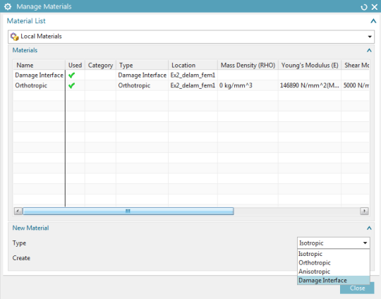
Figure 2: Defining a “Damage
Interface”-type material
Enter the fracture toughness and stiffness for each of the 3 failure modes: these properties are derived from tests. In this case, we use an exponential-type damage law. See Figure 3:
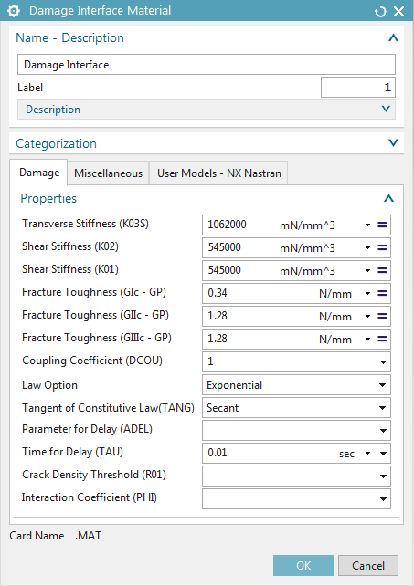
Figure 3: Interface constitutive behavior and
properties
2.
Create cohesive elements between plies
In the “Layup Modeler”, shift-select two ply groups and click the “Create New Cohesive Layer” button.
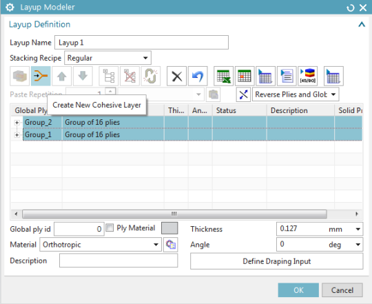
Figure 4: Create a cohesive layer
Then, assign the previously created “Damage Interface”-type material to the cohesive layer. This is illustrated in Figure 5.
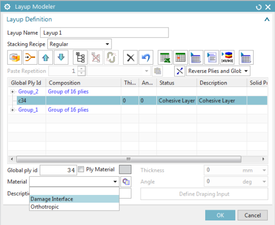
Figure 5: Assign the created material to the
cohesive layer
Setting up the simulation
1.
Create the simulation and solution
Create a new Simcenter Multiphysics simulation and solution, keeping “Automatically Create Step or Subcase” checked:
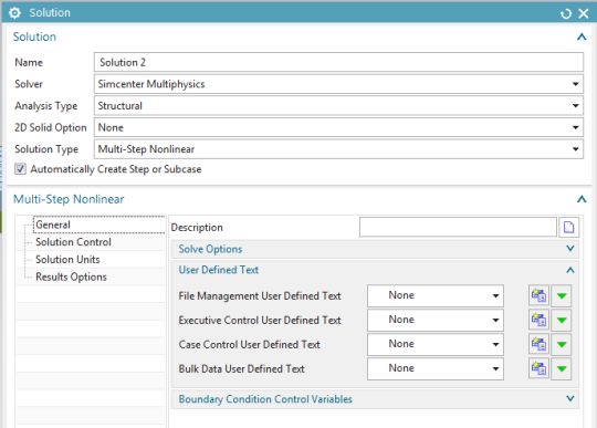
Figure 6: Create a Simcenter
Multiphysics solution
In the “Solution Control” tab, check the “Material Nonlinearity” box (See Figure 7).
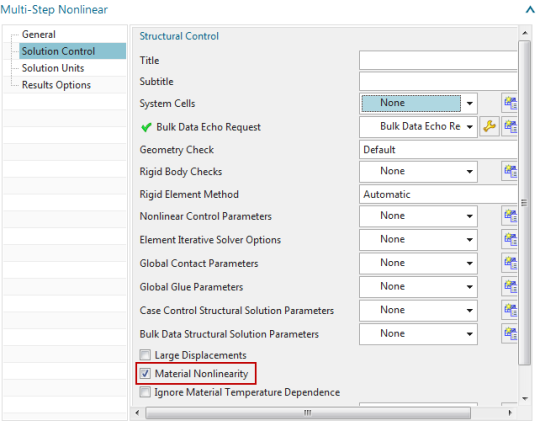
Figure 7: “Solution Control” tab
From the “Result Options” tab, edit the “Structural Output Request” (see Figure 8):
- Set the “Damage” of the Cohesive Element Results to “DAMAGE”.
- Set the “Output Medium” of the Cohesive Element Results to “PLOT”.
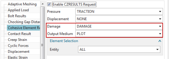
Figure 8: “Output Request” menu
2.
Define the boundary conditions
The -X face of the coupon is completely fixed, while Mode 1 delamination is solicited by defining equal and opposite 1 mm displacements to the top and bottom nodes of the +X face. This is shown in Figure 9 and Figure 10.
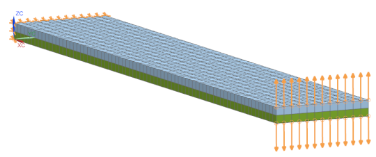
Figure 9: Fixed Constraints and Enforced
displacements
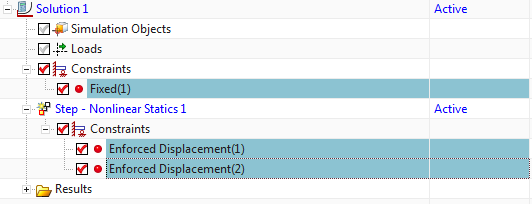
Figure 10: Constraints in Sim Navigator
3.
Define the time step
To define the time integration parameters, select the “Step – Nonlinear Static” node in the sim navigator, then right-click “Edit”, and in the “Time Step Definition” tab, set the “End Time” to 1 sec and the “Number of Increments” to 20. See Figure 11 and Figure 12.
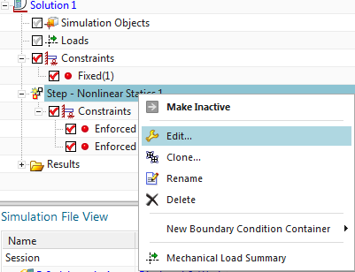
Figure 11: Edit the time integration controls
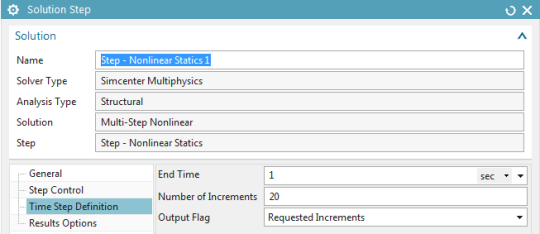
Figure 12: Specify solution time and time step
4.
Run the simulation and animate the damage results
Next, launch the solution and subsequently load the “Cohesive Damage [EXPO] – Element Nodal V1” results. In the “Post Processing Navigator – Fringe Plot”, display only the cohesive elements, as shown in Figure 13:
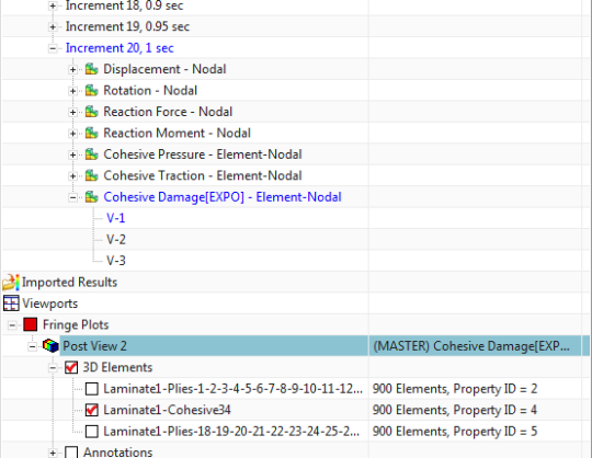
Figure 13: Display the cohesive elements
To animate the results across all the iterations of the nonlinear solution, use the “Animate” button in the ribbon bar. A damage value of 1 indicates a complete delamination of the plies. Use the animation options shown in Figure 14:
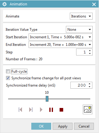
Figure 14: Animate the results
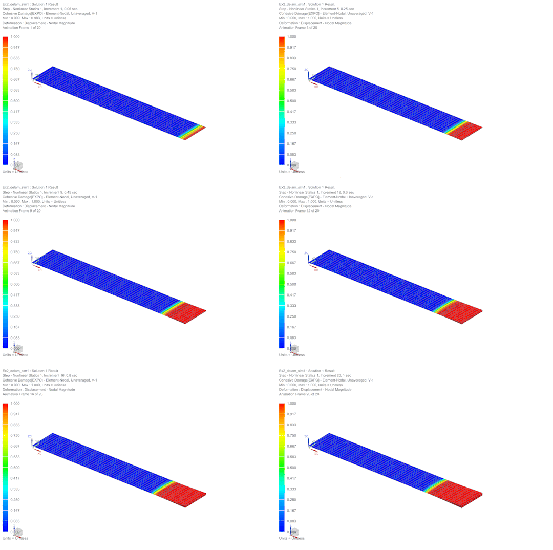
Figure 15: Animation of the
delamination results.
