Quick Overview
Simcenter Laminate Composites (LC) allows you to optimize the fundamental properties of a laminate coupon- for example, increasing its modulus in the X direction, minimizing its mass or its thermal expansion- by modifying ply angles, ply thickness, ply materials or by removing plies.
Core content
The optimization works on a single laminate physical property and involves three components: design variables, design constraints, and design objectives. The property does not have to be assigned to a collector.
Design variables
LC supports the following types of design variables for the plies of a laminate property:
- Ply thickness
- Ply angle
- Material assigned to the ply
- Ply existence, ie whether or not a ply can be removed from the laminate
Ply thickness and ply angle design variables can be either discrete or continuous. Ply materials and ply existence are inherently discrete design variables.
Design Constraints
LC supports the following types of design constraints on a laminate:
- The total mass of the laminate
- The buckling factor for a plate of a given coupon size
- The ply failure index
- The natural frequency for a plate of a given coupon size
- The ply contiguity
- The equivalent laminate X and Y Young’s modulus
- The equivalent laminate shear modulus
- The equivalent laminate Poisson’s ratio
- The equivalent laminate X, Y, and XY thermal expansion coefficients
Design objective
LC supports the following design objectives:
- The total mass of the laminate
- The buckling factor
- The equivalent laminate X and Y Young’s modulus
- The equivalent laminate shear modulus
- The equivalent laminate Poisson’s ratio
- The equivalent laminate X, Y, and XY thermal expansion coefficients
Steps
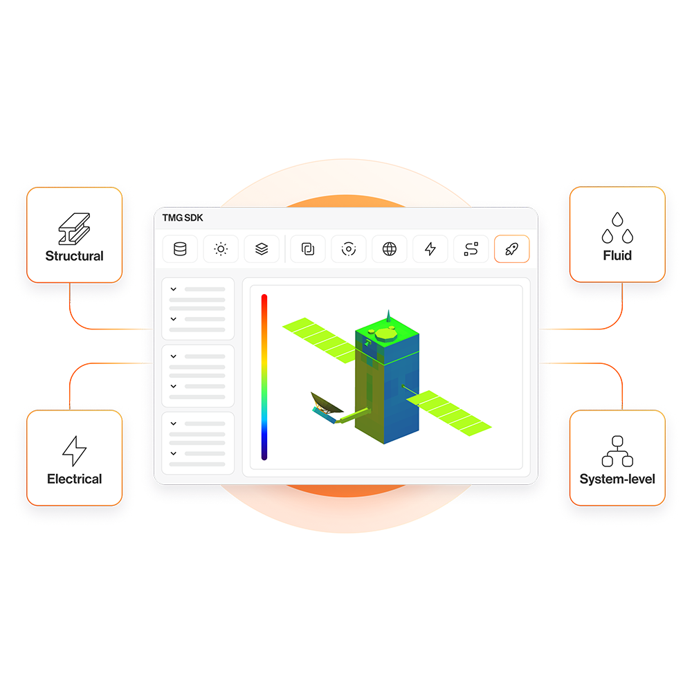
In this example, we are going to use LC to minimize the mass of a deployed solar array with constraints on the minimum natural frequency and equivalent longitudinal stiffness of each individual solar array panel. The design variables are the ply thickness, ply angles, and ply existence. LC optimization is well suited for the flat, rectangular geometry of the array panels, even if the assumed boundary conditions are not fully representative of the actual design.

Figure 1
Spacecraft with deployed solar panels
Each solar array panel is initially designed with a 12 mm thick aluminum honeycomb core, and symmetric 4-ply CFRP face sheets [0/45/90/-45]s, in which each ply is 0.127 mm thick. The initial design has a mass of 0.77 kg, an equivalent longitudinal stiffness of 8.79 GPa, and a natural frequency of 76 Hz. The optimum design should have an equivalent longitudinal stiffness similar to or greater than the initial design and with a natural frequency of at least 20 Hz.
Define the laminate
To define the laminate properties, In the Laminate tab click
Laminate Physical Property to define the laminate layup.

Figure 2:
Define laminate layup

Figure 3: The initial design of solar array
laminate.
First, we need to define design variables. In the Laminate Modeler dialog under the Optimization group check Enable Optimization. As a result, a new group is displayed under the ply layup definition table.

Figure 4:
Enable laminate optimization
Define design variables
The design variables for this example are ply angles, ply thickness, and ply existence. To define a design variable for a ply angle, under the Design
Variable Manager group, set the Type to Ply Angle and click

In the design variable specification dialog, specify a name for this design variable, set the Domain Type to Continuous, and set the Min and Max to -90 and +90, respectively. Click
OK.

Figure 5:
Define design variable for the angle of ply 1
Since the angle of each ply can vary independently from the other plies, we need to repeat this process 4 times to define ply angle design variables for each ply. Note that we do not need a ply angle design variable for the core.
To define design variables for ply thickness, under the Design Variable
Manager group, set the Type to Ply Thickness and click

In the design variable specification dialog, specify a name for this design variable, set the Domain Type to Continuous, and set the Min and Max to 0.0508 mm and 0.254 mm, respectively. Click OK.

Figure 6:
Define design variable for the thickness of ply 1
Similarly to the ply angle design variables, we need to repeat this process 4 times to define ply thickness design variables for each ply. For the core ply, create an additional ply thickness design variable, where the limits of Min and Max are 8 mm and 25 mm, respectively.
To assign design variables to a ply, in the Laminate Modeler dialog, select the ply and under the Assign Design Variable group, select the relevant ply angle design variable from the Angle DV drop down menu, which lists all the defined ply angle design variables. Similarly, to assign a ply thickness design variable use the Thickness
DV drop down menu, which lists all the defined ply thickness design variables. Repeat the above process and assign the relevant design variables to all the plies, including the core ply.
We want to keep the outer ply for the final design, but the rest of the plies can be removed by the optimization algorithm. To identify plies 2, 3, and 4 as removable, select them and check Removable Ply.

Figure 7: Assign design variables to a ply
Note that when a design variable is assigned to a ply, an asterisk appears in the relevant column of that ply. For example, in Figure 7, it can be seen that an asterisk is added beside the thickness and ply angles for ply 1. Also for plies 2 to 4, there is an asterisk beside the ply id, indicating these plies are removable.
Define objectives and
constraints
Under the Optimization group, click

to open the Laminate Optimizer dialog.

Figure 8:
Laminate Optimizer Configuration dialog
In the Laminate
Optimizer Configuration dialog, under the Opt Design Space tab, and under the Objectives group, click

to define the objectives. In the
Objective Specification dialog, set the Type to Total Mass and set the Rule to Minimization, and click OK.

Figure 9:
define design objective
To define the constraint, in the Laminate Optimizer Configuration dialog, under the Opt Design Space tab, and under the Constraints group, click

In the Constraint Specification dialog, set the Type to Natural Frequency, and set the Rule to Greater or Equal to Limit. In the Limit box enter 20 Hz and click OK.

Figure 10:
Define design constraint on minimum natural frequency
Repeat the process above and create a new constraint that the minimum Young’s Modulus along X direction should be greater than 6.67 GPa as shown in Figure 11.

Figure 11: Define design constraint on minimum
Young’s Modulus
Then, under the Plate
Properties group, enter the plate size as 1050 mm for Side A and 325 mm for Side B. Click Ok.

Figure 12:
Plate properties
Note: The optimization in LC has two optimization algorithms: Standard and Hybrid genetic algorithm. The parameters for the optimization algorithms can be tuned under the Operators, Basic Params, and Advanced
Params Tabs. In this Tips and Tricks, we will use the default settings.
Launch the optimization process
In the Laminate modeler dialog, under the Optimization group, click

to launch the optimization process. To see the best five optimum candidates and a summary of the optimization results click

which exports the optimization results to a spreadsheet. You can also check the detail box, to have the layup and laminate properties for each of those five optimum candidates.
A summary of the optimization results is shown in Figure 13. It can be seen that optimization algorithm removed 2 plies, reduced the mass by about 58% while satisfying both constraints.

Figure 13: Summary of the optimization results
Finally, using the Results drop-down menu, you can choose one of the candidate optimum designs and the laminate definition is automatically updated to the layup of the selected optimum design (Figure 14).

Figure 14: Select one of the five optimum
candidates