Quick Overview
Sandwich panels are prevalent in many structural applications. The panel facesheets react the membrane and bending loads, whereas the core reacts the bulk of the transverse shear loads. Therefore, you may use the solid mesh to get better results in the ply out-of-plane direction to evaluate delamination and also investigate the local sandwich behavior near the tapered core.
This tips and tricks shows how to use Simcenter Laminate Composites to create a 3D mesh of a tapered laminated composite sandwich car hood.

Figure 1:
Car hood CAD model. Top face (left). Bottoms face (Right).
Steps
1-
Create a 2D mesh
First, we create the parent 2D mesh on the car hood top face and that will be extruded to a 3D mesh. To create the 2D mesh, go to Home tab, under Mesh group, select 2D Mesh command to create a 2D mesh on the top face of the car hood.
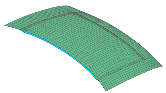
Figure 2:
Create 2D mesh on the car hood top face.
We use a ply-based approach to define layups’ global plies and how they drape on the model. In the Laminate tab, select Laminate Physical Property. In the Laminate Modeler dialog, set the stacking recipe to Inherited from layup and click OK.
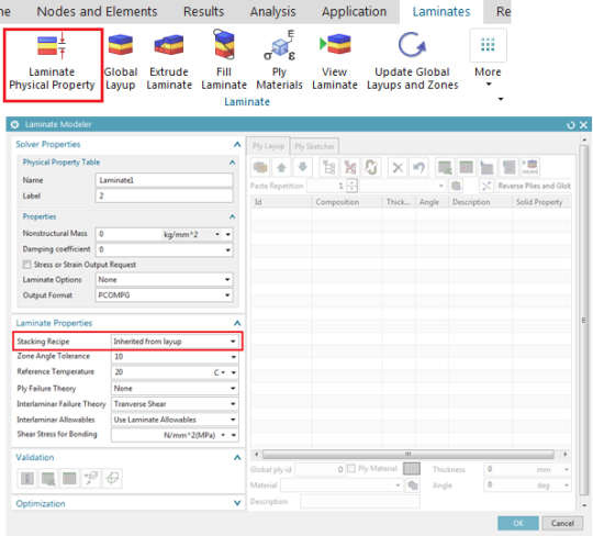
Figure 3: Create a Laminate Physical Property.
Let’s assume a simple quasi-isotropic [0/45/-45/90]s layup with a 12.7 mm thick foam core, which is tapered around the perimeter of the hood.
In the Laminate tab, select Global Layup and then in the Layup Modeler dialog, select the Import Layup Using Shorthand Format.
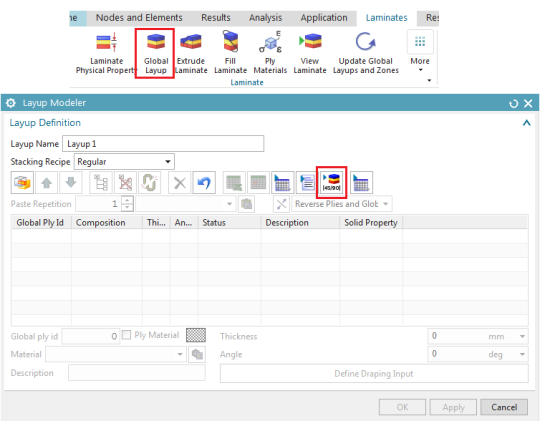
Figure 4:
Create a Global Layup.
In the shorthand Format dialog enter the layup as [0/45/-45/90/0’]_s, set the Thickness to 0.125mm and the Material to CFRP.
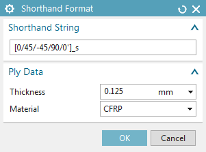
Figure 5:
Input the layup using shorthand format.
In the Layup Modeler dialog, verify the Stacking Recipe is Symmetric with core, change the material for Ply 5, which is the core, to foam and change its thickness to 12.7mm.
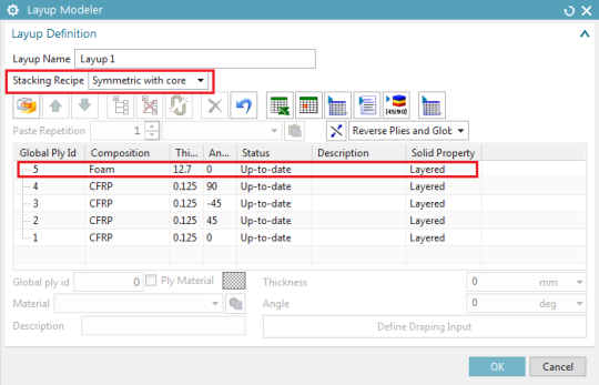
Figure 6:
Layup definition in the Layup Modeler dialog.
To drape the plies, shift-select plies 1 to 4 and click on the Define Draping Input command. In the Draping Data: Layup Files dialog, select the entire top face of the car hood, and click OK.
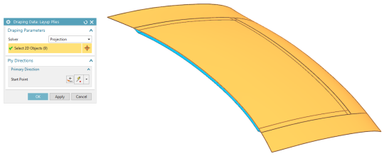
Figure 7:
Drape the plies on the car hood.
In the Layup Modeler dialog, select the core ply and then click on Define Draping Input command. This time select the face(s) on which the core ply is going to be laid up.

Figure 8:
Drape the core ply.
The 2D layup is now defined and properly draped. To automatically inflate this layup to a 3D mesh, go to the Laminate tab, select Extrude Laminate command.

Figure 9:
Extrude laminate command.
In the Laminate
2D-to-3D Extrusion dialog, under the Settings group, select all the faces of the car hood on which the 2D laminate is draped.
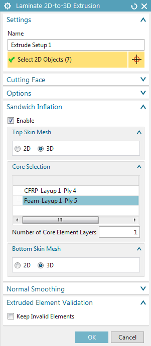
Figure 10:
Laminate Extrusion settings.
Under the Sandwich
Inflation group, Set the Top Skin
Mesh and Bottom skin Mesh to 3D and select the core ply from the list. Here you can also optionally set the Number of Core Element Layers. Click Ok.
As shown in Figure 11, the 3D solid mesh for the car hood is created. Drop-off resin elements are automatically created where the core tapers. The drop-off resin elements are created as a separate mesh entity. You can drag the resin meshes to be under the same collector as the core meshes.
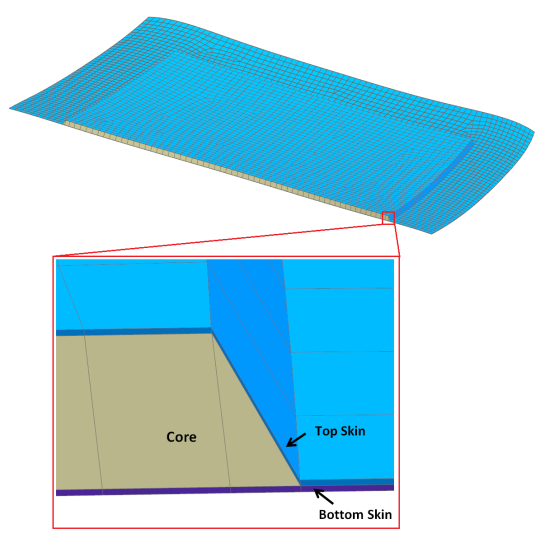
Figure 11: 3D mesh created for the laminated
composite car hood.
