Quick Overview
This Tips & Trick shows how you can overlay the critical ply ID and load case ID on laminate element contour plots using Advanced Post Report in NX Laminate Composites (NXLC). The critical ply ID and load case ID can be obtained for ply stresses, ply strains, failure indices, strength ratios and margins of safety.
Core content
In this Tips & Trick, we will assume that you have already solved your model and obtained the ply stresses and ply strains. The main steps to follow for showing the critical ply ID and load case ID are:
- Create an Advanced Post Report in NXLC.
- Create a Graphical Report and select the desired types of results.
- Generate the result file.
- Select the desired results in NX Post and display the critical ply ID and/or load case ID from the Post View.
Steps
Create and Advance Post Report in NXLC
In the Laminates tab, click on Advanced Post Report as shown in Figure 1.
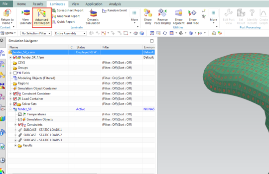
Figure 1: Creating an Advance Post Report in NXLC.
Select the load cases you want to analyze. In this example, we select all load case (3). Click Ok.
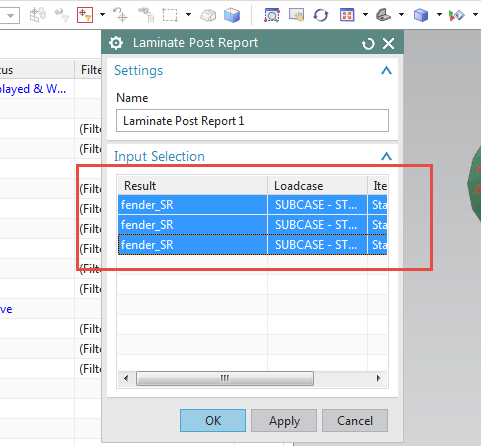
Figure 2: Selection of the load cases.
The Laminate Post Report node will appear in the navigator.
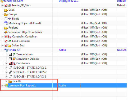
Figure 3: A Laminate Post Report node appears in the Sim Navigator.
Create a Graphical Report.
Right-click on the Laminate Post Report node and select Create Graphical Report.

Figure 4: Create a Graphical Report.
The graphical report dialog will appear as shown in Figure 5.
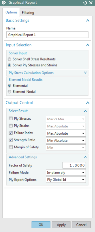
Figure 5: Graphical Report UI.
Different options are available:
- Solver Input: Choose if you want to compute the ply stresses and strains from the shell resultants or use the ply stresses and strains already available in the results file. In this example, we choose the second option.
- Elemental Nodal Results: Choose between elemental and elemental-nodal results. In this example, we choose elemental results.
- Select Results: Select the type of results you want to process, as well as how you want the results sorted. In this example, we select the maximum absolute sorting for failure index and the minimum absolute sorting for strength ratio.
- Advanced Settings: Select the failure mode (ply, interlaminar or both) as well as the ply ID display (layer or global ply IDs) option. In this example, we compute in-plane (ply) failure and we wish to display global ply IDs in the sim navigator.
Click on OK to close the Graphical Report UI. A Graphical Report node will appear in the navigator.
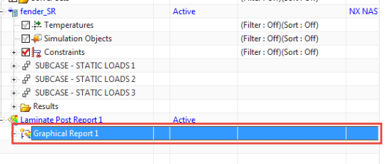
Figure 6: A Graphical Report node appears in the Navigator.
Generate the result file
Right-click on the Graphical Report node and select Generate Result File.

Figure 7: Generation of the result file.
The results will appear in the Post-Processing Navigator.
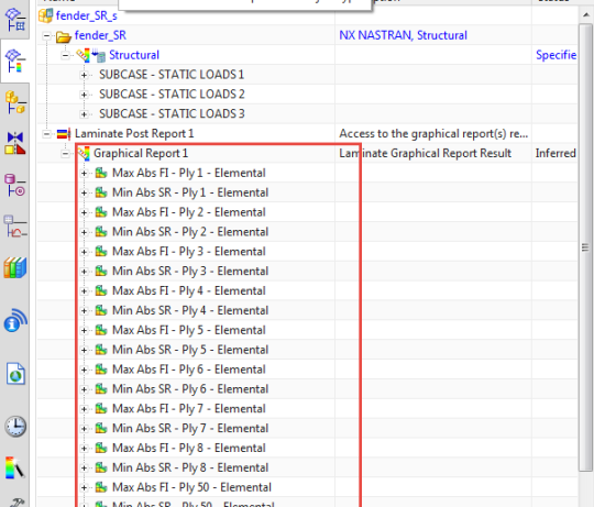
Figure 8: List of results in the Post-Processing Navigator.
The results are shown over all load cases by ply, and over all the plies.
Show the critical ply ID and load case ID
It is possible to show the critical load case ID for a given ply or the critical load case ID and critical ply ID over all the plies.
For instance, if we want to show the critical load case ID for ply 55 strength ratio results, double-click on the result in the navigator under Min Abs SR – Ply 55 – Elemental. Then right-click on Post-View and select Show Critical Loadcase ID.
If we want to overlay the critical ply ID on the failure index contour plot, double-click on the result in the navigator under Max Abs FI – Elemental. Then right-click on Post-View and select Show Critical Ply ID.

Figure 9: Critical load case ID for ply 55 strength ratio results.
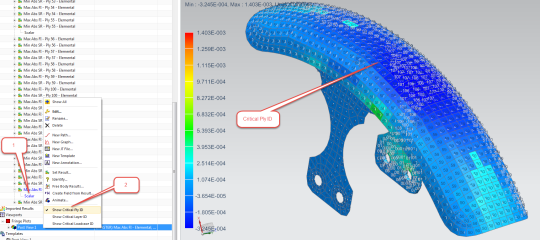
Figure 10: Failure Index Critical ply ID .
