Quick Overview
This Tips & Trick shows how you can define your own ply and interlaminar failure theories in NX Laminate Composites.
The main steps are:
- Create and set a new project in Microsoft Visual Studio.
- Code the failure theory and build the corresponding Dynamic Link Library (DLL).
Steps 1 and 2 should be repeated for each failure theory.
- Create an XML file that defines the names of the user-defined failure theories and the path to the DLLs.
- Link NX Laminate Composites to the XML file.
- Select the user-defined failure theories in NX Laminate Modeler.
Core content
We will define a ply failure theory called “USER_TSAI_WU” as well as an inter-laminar failure theory called “USER_TRANSVERSE_SHEAR”. IN this example, we will be using a C++ environment: You can also code in C or Fortran.
Steps
Create and set a new project in Microsoft Visual Studio.
In Microsoft Visual Studio, go to File->New Project.
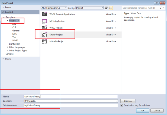
Figure 1: Creating a new project in Microsoft Visual Studio.
Make sure to set the configuration to x64:
- In the Solution Explorer pane, right-click your project and select Properties.
- Click Configuration Manager.
- Under the Active solution platform drop-down menu, click New.
- Select x64 in the first drop down.
- Click OK, until you’re back at the project Property Page.
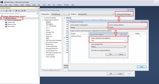
Figure 2: Changing the configuration to x64.
From the project Property Page, change the project type to DLL under General->Configuration Type.
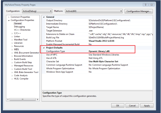
Figure 3: Change the project type to Dynamic Library (.dll).
Some header files needs to be included in the project. These headers define how a failure theory should be coded. The headers are located in:
$NX_BASE_DIRECTORYNXCAE_EXTRASlaminateUserFTinclude
This path has to be specified in the project Property Page under C/C++ -> Additional Include Directories.
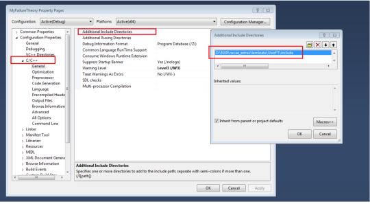
Figure 4: How to specify the path of the header files in the project property page.
Finally, add a C++ source file. Right-click on your project and select Add->New Item->C++ File.
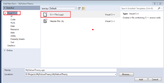
Figure 5: How to add a C++ source file in Visual Studio.
Code the failure theory and build the DLL
The failure theory should be coded by following the templates defined in the header files “UserFailureTheory.h” and “UserFailureTheoryTypes.h” (included in the Visual Studio project – see previous step). Two functions templates are defined:
- int EvaluatePlyFailure (… arguments …)
- int EvaluateInterlaminarFailure (… arguments …)
If the user-defined theory is a ply failure theory, the first function needs to be implemented. If the user-defined theory is an inter-laminar failure theory, the second function should be coded. Both functions take several arguments like the material type, the element type, the ply location, the stress and strain tensors, the stress and strain limits, etc. The functions return 0 if the computation succeeds and 1 if it fails.
The figure below shows a snapshot of the function “EvaluatePlyFailure”.
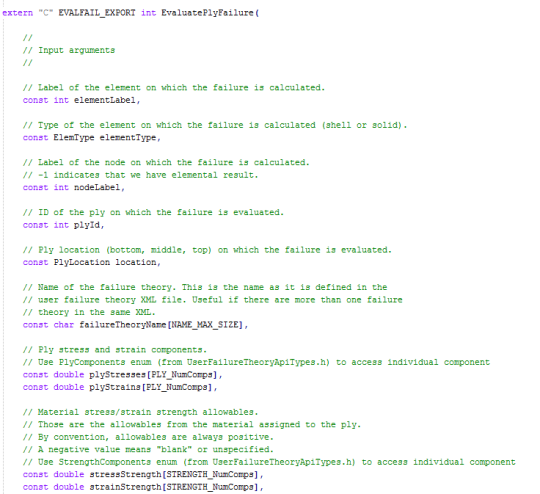
Figure 6: Snapshot of the function “EvaluatePlyFailure”.
Create an XML file
Once both failure theories have been coded, the source files can be compiled through two separate Dynamic Link Libraries (DLLs):
- User_Tsai_Wu.dll
- User_Transverse_Shear.dll
Let’s assume that the DLLs are placed in a directory called “User_Defined_Theories”.
An XML file should now be created. This XML file provides a name for each failure theory and points to the corresponding DLL. A template of such an XML file can be found under:
$NX_BASE_DIRECTORYNXCAE_EXTRASlaminateUserFTxmlTemplate.xml
The XML should be modified as shown below:
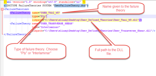
Figure 7: XML file that defines the name of the failure theories and provides the path to their corresponding DLL.
In this example, the name of the XML is “UserFailureTheory.xml” and is located in the same directory as the DDLs files.

Figure 8: The XML file and the DDLs are placed in the directory User_Defined_Theories
Link NX Laminate Composites to the XML File
NX Laminate Composites needs to point to the XML file. This can be done in the Customer Defaults settings. Under Simulation->Laminate Modeling, put the full path of the XML file under “User Defined Failure Theory XML Config File”, as shown in the figure below.
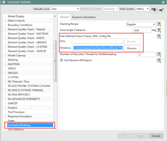
Figure 9: Customer Defaults settings
Use the failure theories in the NXLC modeler
The failure theories can now be selected in the NX Laminate modeler:
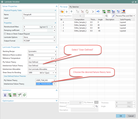
Figure 10: NX Laminate Modeler
Now you can process the ply stress or strain tensor from any NX-supported solver like NX Nastran, MSC.Nastran, Ansys, Abaqus, LS-Dyna and Samcef. NX Laminate Composites will compute the failure metrics (failure index, strength ratio and margin of safety) using the code you generated and will output the results exactly in the same way that it does for ‘out-of-the box’ failure criteria:
- As Laminate Post spreadsheet reports, and
- In NX Post as contour plots.
Figure 11 shows a contour plot that displays the maximum failure index over a part, along with the critical ply ID.
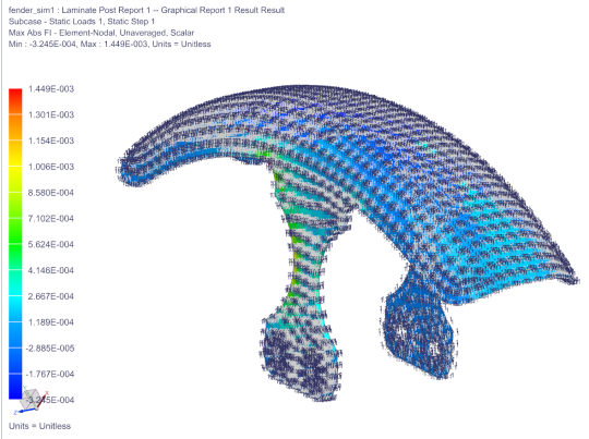
Figure 11: Maximum failure index with the critical ply ID.
