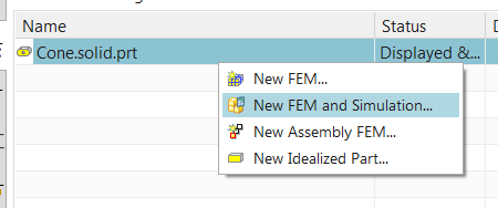
Quick Overview
It is often required to create lightweight, simplified versions of large FEMs in order to reduce solution time or post-processing effort. A common simplification technique that can be used with relatively slender parts is midsurfacing. Whereas plate theory can accurately predict the stiffness of each part, there can be uncertainty at the structural connections be they welded, bonded or fastened- due to the idealization of the part thickness and the creation of non-manifold joints.
Simcenter FE Model Correlation and FE Model Update allow you to compare the modal properties of fine and simplified FEMs, as well as to automatically update the simplified FEM to minimize the differences.
In this example, we’ll take a relatively large FEM of a cone with 2 welded flanges as reference, and update a simplified, midsurfaced version of the FEM so that the modal frequencies agree well. The simplified model will provide the work solution. We’ll also create the 2 FEMs.
Core content
Create Reference FEM
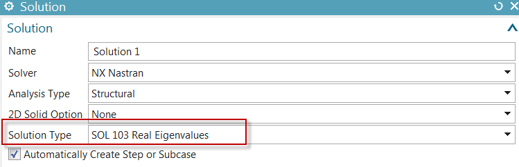
Starting with the CAD geometry, we first create the larger reference FEM and SIM, using NX Nastran as solver:
Set the Solution Type to SOL 103 Real Eigenvalues
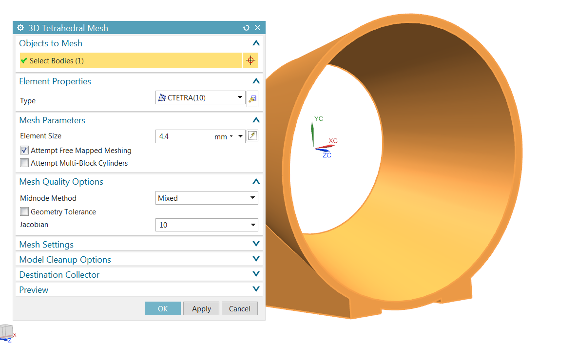
Create a parabolic tetrahedral mesh of the part using the default size computed by Simcenter:
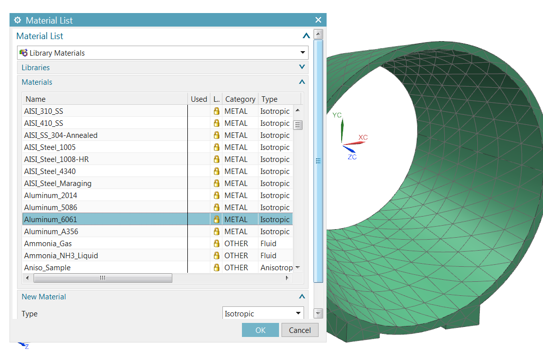
As material, select Aluminum_6061 from the Simcenter materials library
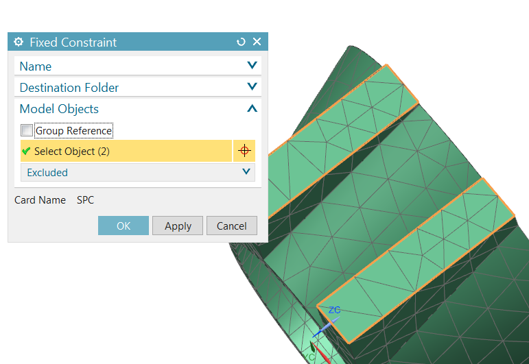
Make the SIM the work part, select the 2 bottom faces of the flanges to define fixed constraints:
Solve the normal modes Solution. 10 modes are computed, the first being at 1318 Hz.
Create Work FEM
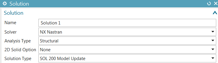
Go back to the part file in the modeling application. Create a new NX Nastran FEM and SIM, and set the Solution Type to SOL 200 Model Update
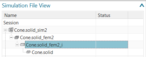
Using the Simulation File View, navigate to the idealized part.
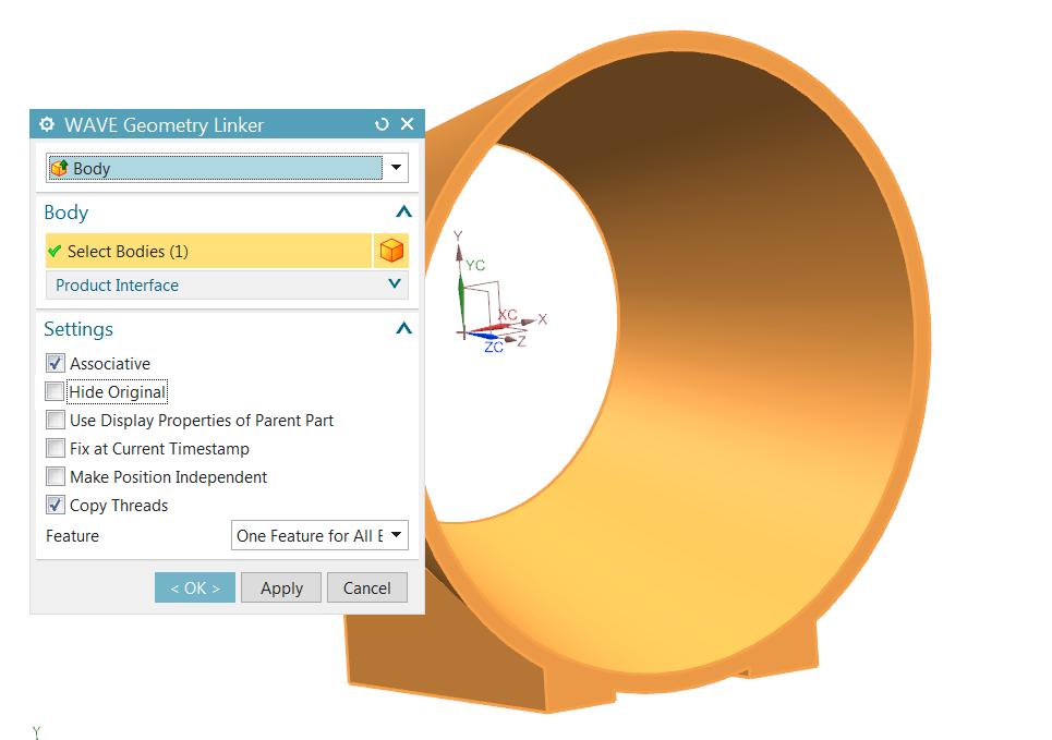
Create an associative copy of the CAD part using WAVE linking. Do not hide the original part.
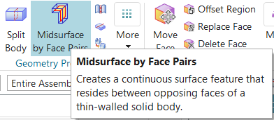
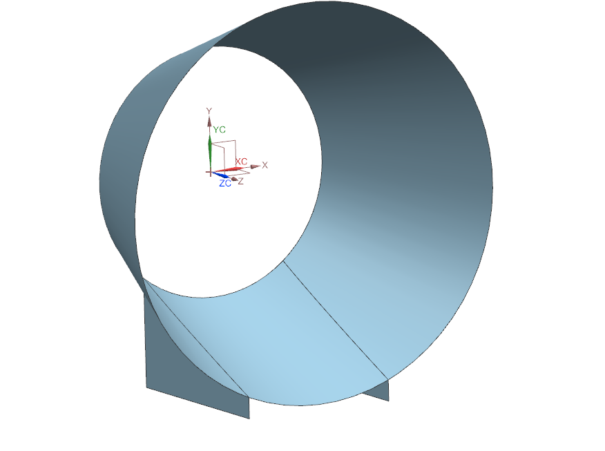
Click Midsurface by Face Pairs
Select the solid body and click Automatically Create Face Pairs. The midsurfaced part looks like this
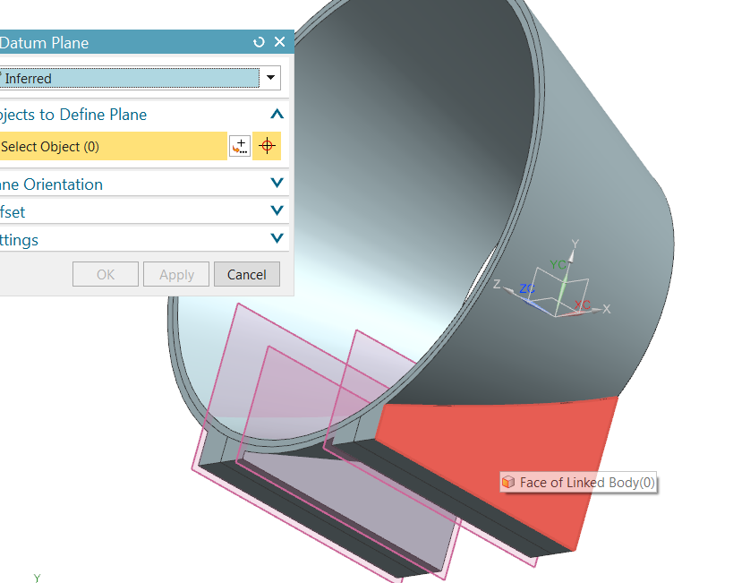
Create 4 datum planes, one on each vertical face of the 2 flanges
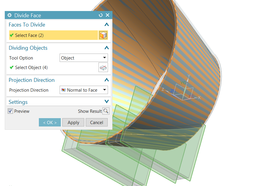
Divide the cone sheet body faces using the datum planes to create 4 new faces around the flange joints. The meshes on these faces will be assigned a material property which will be used by FE Model Update.
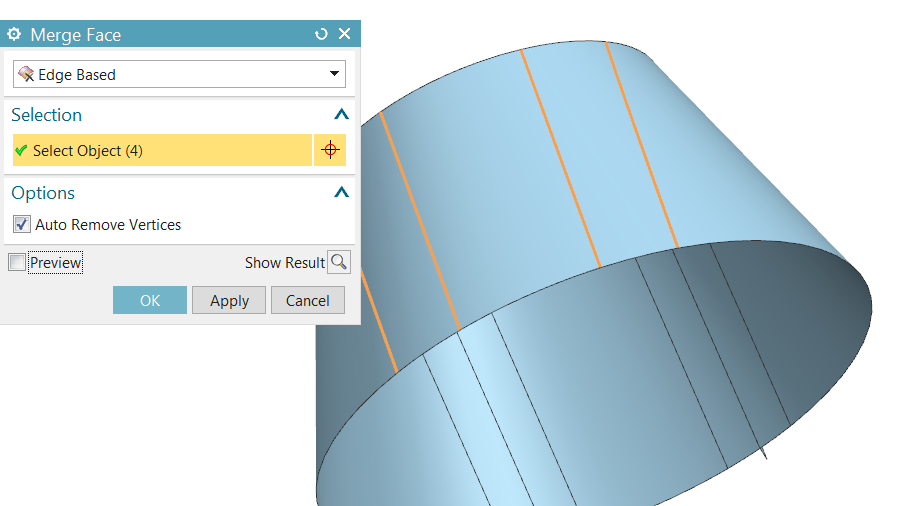
Return to the fem. Hide the original polygon geometry, keeping the newly created sheet bodies. Use Merge Faces to get rid of the unneeded divisions on the top of the cone
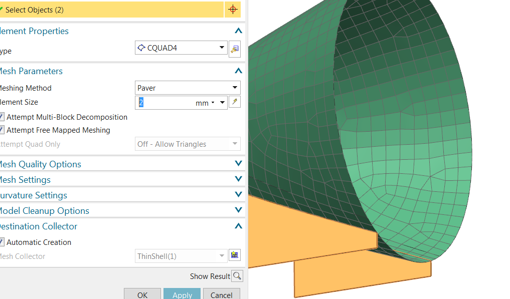
Use Automatic Stitch Edge to merge the coincident edges of the flanges and the cone. Create 3 different 2D meshes and place them in the following collectors:
1- A collector for the general cone section
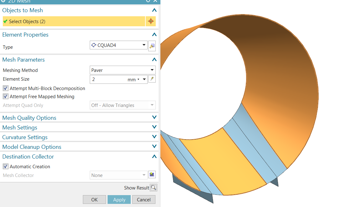
2- A collector for the joint section which will be optimized.
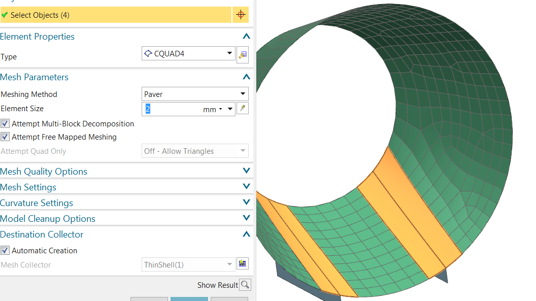
3- Finally, a collector for the flanges
Shift-Select the 3 meshes in the sim navigator, Edit Mesh Associated Data,
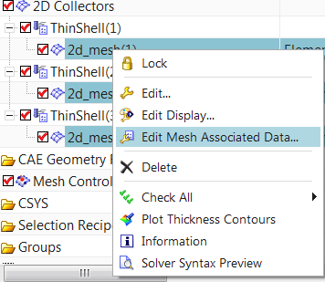
And set the thickness source to Midsurface.
Select the general cone section collector, Edit the PSHELL1 property and select Aluminum_6061 as material. Select the flange collector, and assign PSHELL1 to it. Then select the joint section collector, Edit the PSHELL2 property, and assign to it a copy of Aluminum_6061 which you rename OPTIM.
Go the SIM.
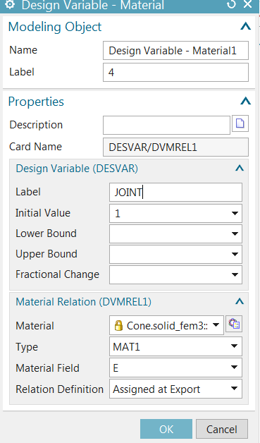
Create a new Material Design Variable
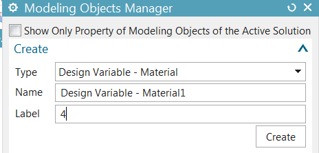
Select OPTIM and its field E (Modulus) as design variable.
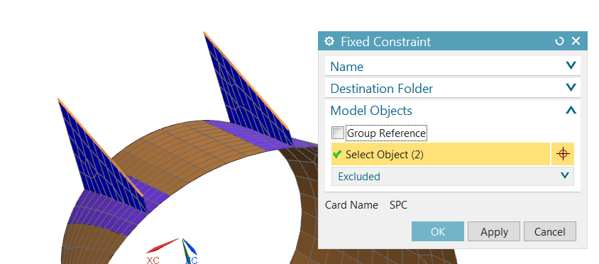
Create fixed constraints at the base of the 2 flanges
Edit the solution. In the Bulk Data tab, Create Design Variables
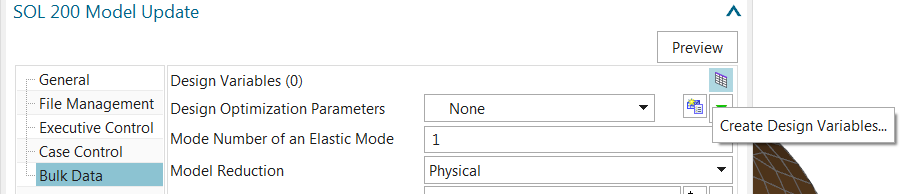
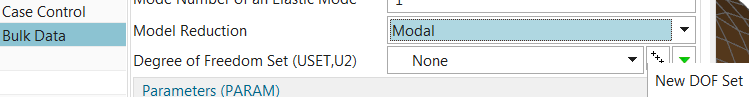
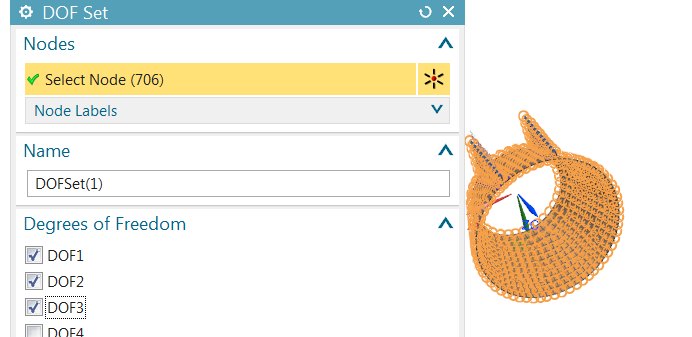
Add to the active list the variable you just created. Set the Model Reduction method to Modal, and create a New DOF set
Select all the nodes in the FEM, and check DOFs 1, 2 and 3
Solve the solution. Note the first mode is at 1053 Hz.
Correlate Work and Reference Models
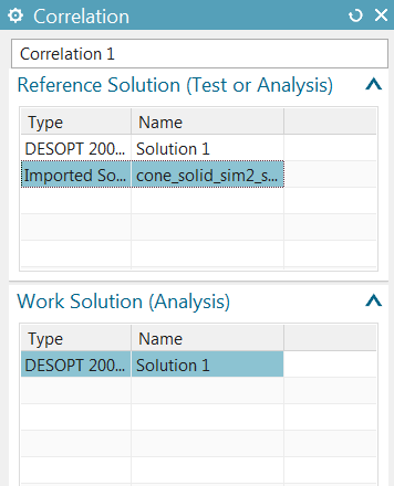
In the Correlation tab, create a New Analysis Reference Solution.
Select the .op2 file from the SOL 103 solution using the reference FEM.
In the Correlation tab, create a New Correlation and select the Work and Reference solutions
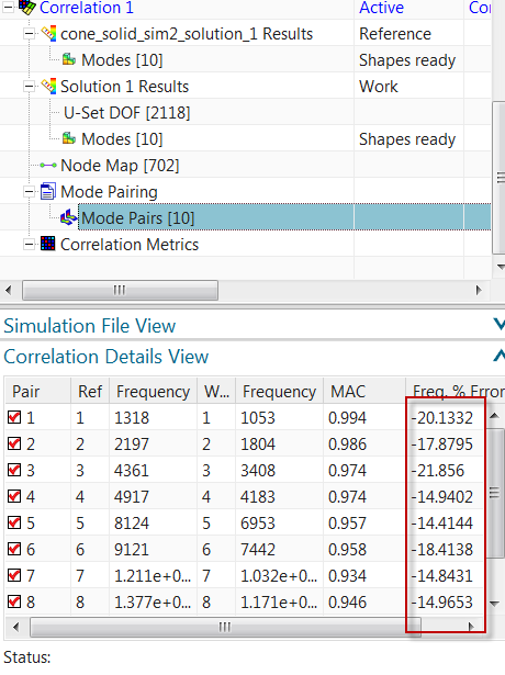
Select the Mode Pairs node in the SIM navigator, open the Correlation Details View, and notice there are significant frequency errors between both models. However the mode shapes correlate very well, as indicated by the high MAC value for each mode pair.
Model Update
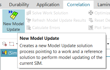
We will now optimize the work model to improve the correlation with the reference model. Create a New Model Update
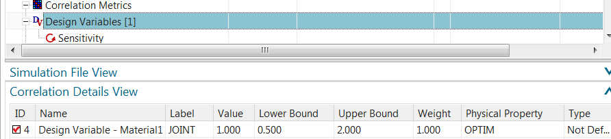
Select the same solutions as for the Correlation. Notice the single design variable is displayed with an initial, normalized value of 1
In the Model Update group of the Correlation tab, click Optimize
Since we’re not concerned about limiting the change in the design variable, set the Overall Design Variable Weight to 1%
The optimization ends with the design variable reaching its default upper limit of 2:

Comparing Current and Initial frequency errors, we notice an improvement, which is not as significant as expected because of the limit on the design variable.
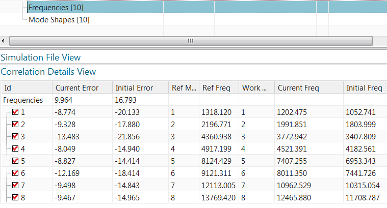
We can edit the design variable’s Upper Bound and set it to 4

After optimization, we notice a much better correlation
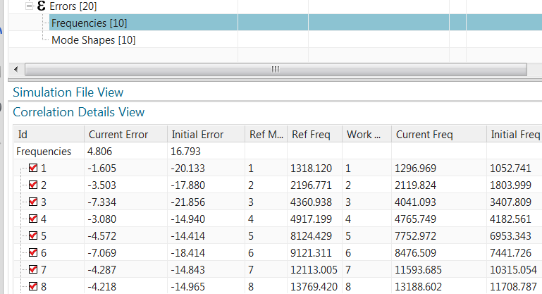
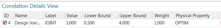
The JOINT design variable’s normalized value is now 3.
This means the Young’s Modulus of the OPTIM material has tripled, which is a substantial change. Since SOL 200 Model Update Solution returns first-order sensitivities which are valid for small changes, the solution needs to be updated. In the Model Update group of the Correlation tab, click Update Finite Element Model. This command automatically updates the material and physical properties in the FEM.

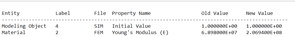
The new value of E for material OPTIM is 2.07 X10⁸ kPa, from the original value of 6.98 X10⁷ kPa
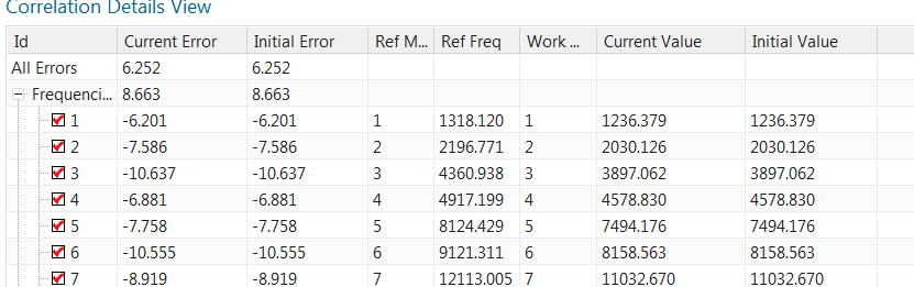
Re-solve the SOL 200 Model Update solution, Reset the Design Variable to 1 using the Reset command and Refresh the Model Update. We notice that the frequency errors are different than after the previous optimization, this is because of the linear sensitivities:
Optimize once again

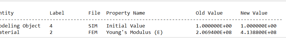
Let’s now Update the FEM. The new value of E is 4.14 X10⁸ kPa.
Re-solve the SOL 200 Solution and Refresh the Model Update. The frequency error for the first mode pair is less than 1%, it was originally around 20%. Side-by-side mode shape displays complement the Correlation Details View.
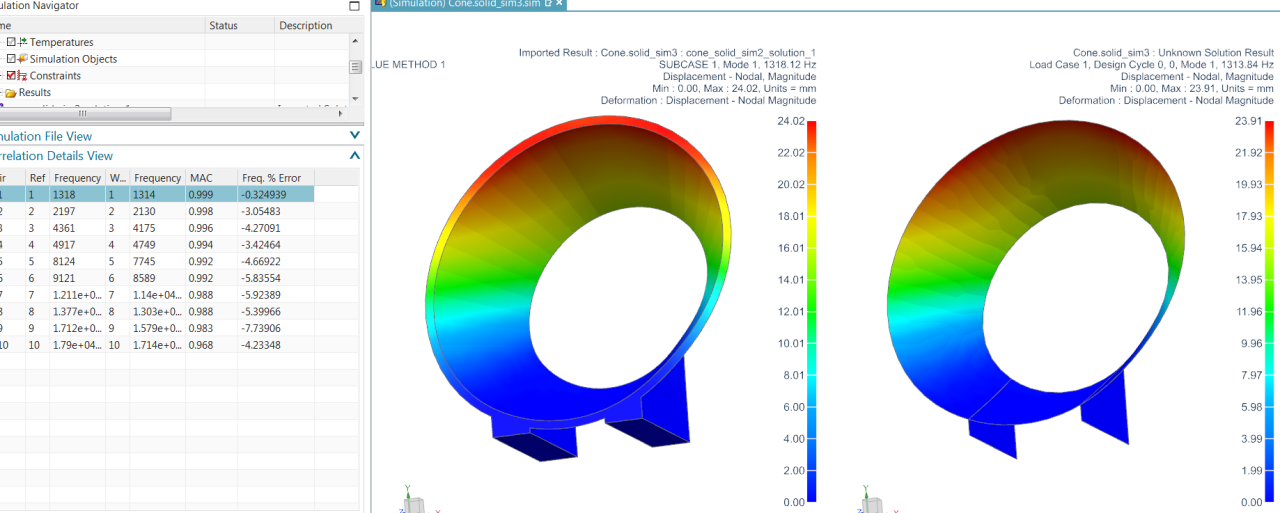
All MAC values are above 0.96. The largest frequency difference is for mode 9, 7.7%. It was originally around 15%

By changing the optimizer settings, it’s possible to reduce the maximum error for all 10 modes to less than 5%, however this results in an increase in the error for mode 1, which may be the most important mode due to its effective mass. The maximum error can also be reduced by further splitting the faces of the work model and creating more design variables.
Summary
We have validated a simplified FEM that contains 706 nodes (around 3500 dofs) against a finer reference FEM containing 10587 nodes (around 31500 dofs 10 X more than the simplified FEM). In reality the reference FEM should be even finer, such that there are 2 layers of elements through the thickness.
The first mode correlates with a MAC of 1 and a frequency difference below 1%. Other modes also show excellent shape correlation, with a maximum frequency error around 8% for the ninth mode.