Demo Video:
Quick Overview
NX Laminate
Composites (NXLC) allows you to easily define laminates, assign them to 2D or 3D meshes of complex geometries, and post-process composite failure metrics. For simple parts like test coupons, creating a FEM is not required, as NXLC allows you to verify the ability of your laminate to withstand the following loading conditions:
- Membrane forces
- Bending moments
- Transverse shear forces
- Temperature loads
In this example we will determine the loads required to produce first-ply failure in a 4 point bending test coupon as per ASTM D7264. We will compare the NXLC results with those of a shell element FEM with appropriate boundary conditions.
Laminated strip under four-point bending
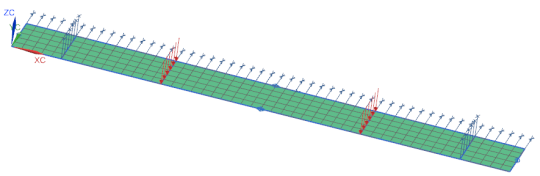
Figure 1:
Laminate strip under three-point bending
A cross-ply laminate with [0/90/0/90/0/90/0] layup is specified with the center ply being four times as thick as the others. With such a lay-up, the bending moment is reacted more uniformly across the section. A model, with appropriate boundary conditions, is used and predictions are obtained using laminated shell elements.
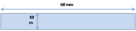
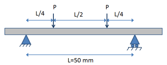
Figure 2: A laminate test specimen under four
point bending
The initial guess at the failure bending moment is 1250 Nmm. The applied moment per unit length is 1250 N.mm/10mm = 125 N
The applied load P = -4M/L = -(4*1250Nmm)/50mm= -100 N.
1.
Determine failure load Using NXLC
Create a new empty FEM, by clicking NEW command.
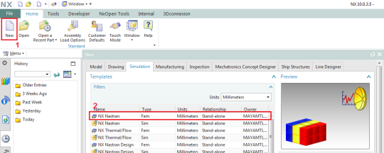
Figure 3:
Create a new FEM
First, we define the material properties to be used in the laminate definition.
Go to Home tab and under the Properties group click on Manage
Materials.
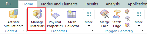
Figure 4:
Manage Materials
In the Manage
Materials dialog, set the type to Orthotropic and click on Create.
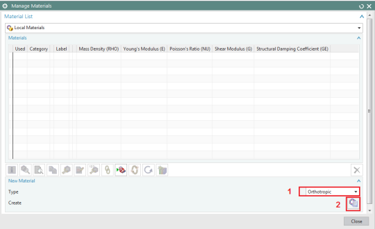
Figure 5:
Define a new orthotropic material
Then define mechanical and strength properties as shown in Figure 6 and Figure 7.
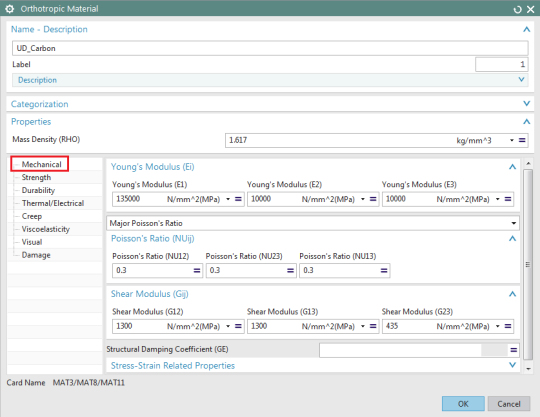
Figure 6: Define material mechanical
peroperties
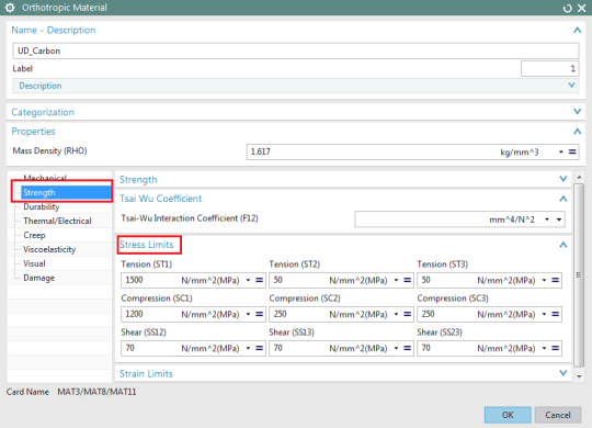
Figure 7: Define material strength properties
To define the laminate, go to NX’s Laminates tab and click the Laminate Physical Property button.
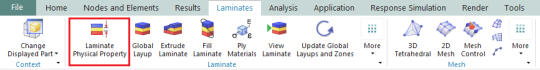
Figure 8: Create a laminate physical property
In the laminate modeler, select Import Layup Using
Shorthand Format button to quickly define the layup.
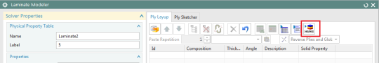
Figure 9:
Import Layup Using Shorthand Format button
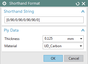
Figure 10:
Shorthand format to define a layup
In the Laminate Modeler dialog, set the output format to PCOMP, and the Ply Failure Theory to Tsai-Wu. Click OK to close the dialog.
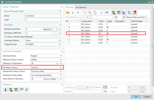
Figure 11: A symmetric quasi-isotropic
laminate [0/90/0/90/0/90/0]
In the Laminate Modeler, under the Validation group, click the Analyze Laminate Strength button.

In the Laminate Strength Analysis dialog, enter the vaue of 125 N for X Bending Moment per unit length and click on Export
Spreadsheet to generate the analysis results.

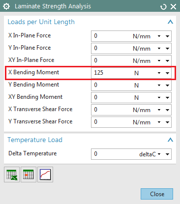
Figure 12:
Define applied load in Laminate strength Analysis dialog
In Laminate 1 spreadsheet, navigate to Strength Analysis worksheet to see the analysis results.
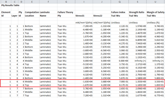
Figure 13:
A preview of a portion of the results generated by NX Laminate Composites.
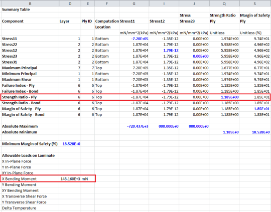
Figure 14:
A preview of a portion of the result summary generated by NX Laminate
Composites.
The minimum strength ratio for all plies is 1.185, which means the coupon will fail at a load of 1.185*1250Nmm=1481.25 Nmm, which is equal to a stress resultant of 1481.25Nmm/10mm=148.125N (shown in the spreadsheet results under the Allowable
Loads on Laminate. Note that the slight difference is due to round off in spreadsheet).
Keep your FEM open in NX.
2.
Determine
failure load using FEM
2.1.
Create the Coupon Geometry
In the simulation navigator, make your part file the work part, and create a rectangular face with dimensions 60 mm x 5 mm, representing a half of the test specimen.
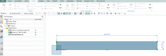
Figure 15:
Create geometry in NX
To create a FEM and Sim, go to Application tab and click the Advanced button.
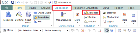
Figure 16:
Create a FEM and Sim
In the sim navigator, right-click on the model and select New FEM and Simulation. Select the sheet body you just created and click OK.
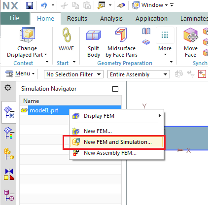
Figure 17:
Create a new FEM and Sim
Then, make the FEM work Part and create a 2d mapped mesh with 1 mm CQUAD4 element size.
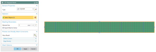
Figure 18:
Meshing the geometry with 2D shell elements
2.2.
Assign
the Laminate Property to the Mesh
Import the physical property and the material you created in your first FEM: From the Menu, Insert, Append FEM:
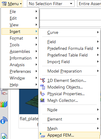
Figure 19:
Append FEM
Your previous FEM name should appear in the Loaded Fem list. Remove the string in the
String to prepend fem object names box, so that it is blank:
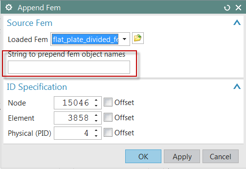
Figure 20:
Append FEM
Then, in the sim navigator, right-click on the mesh collector and select Edit. Then, in the Mesh Collector dialog, set the Type to Laminate, and set the Shell Property to _Laminate 1 (the name of the laminate layup that is defined in Figure 11)
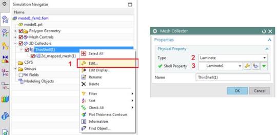
Figure 21:
Assign laminate properties to the mesh
2.3.
Create Simulation
Create the Simulation file by setting the solver to NX Nastran and the solution to SOL 101 Linear Statics – Subcase Constraints.
Make the sim work part. Note that we modeled a quarter of the specimen: Therefore, the applied load in FEM will be 100N/2=50 N to each of the line loads (Figure 2). In the sim navigator, right-click on the Loads node and then select New Load, Force.
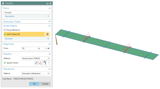
Figure 22:
Apply load along Z-direction
Apply the symmetry boundary conditions to the top (DOF2=0) of the model. Then, fix DOF3=0 along the support lines (Figure 2). To prevent rigid body motion, it is needed to fix the center of the laminate strip (Point A) along X-axis (DOF1=0).
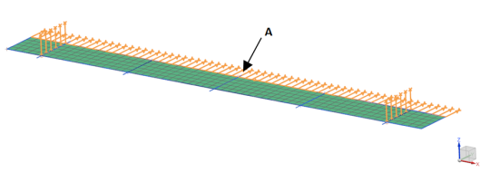
Figure 23:
Apply symmetry boundary conditions
The model can now be solved.
2.4.
Post-Processing
In the Post Processing Navigator, the results are reported for each ply separately. Therefore, we use NX
Advanced Post Report to extract the minimum strength ratio for all the plies.
Go to the laminate Tab, and click Advanced Post Report. In the Laminate Post Report dialog, select the solution name and click OK.
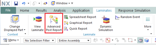
Figure 24:
Advanced Post Report
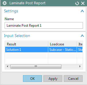
Figure 25:
Laminate Post Report Input selection
In the sim navigator, right-click on the Laminate Post Report 1 node and select Create Graphical Report.
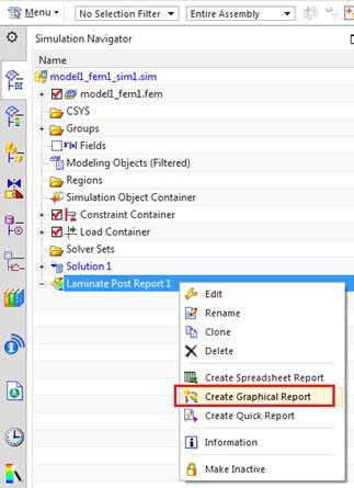
Figure 26:
Create a graphical report
In the Graphical Report dialog, under the Solver Input group, set the solver input to Solver
Ply Stresses and Strains. Then, under the output control group, check the Strength Ratio and set the filter to Min Absolute, and click OK.
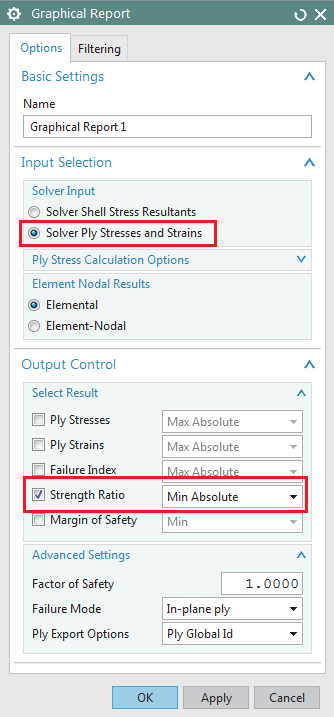
Figure 27:
Graphical Report dialog
In the sim navigator, right-click on the Graphical Report 1 and select Generate Result File.
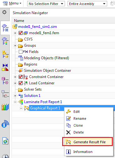
Figure 28:
Generate graphical post result
Switch to Post Processing navigator and expand Laminate Post Report, and select Min Abs SR – Elementa.
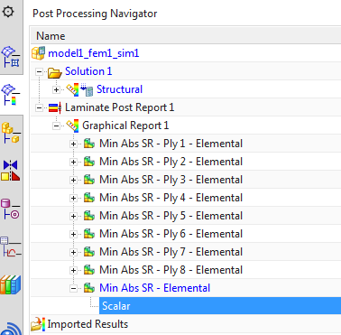
Figure 29:
Min. strength ratio for all the plies
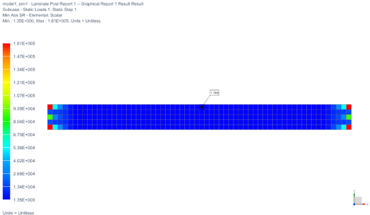
Figure 30:
Min. strength ratio for all the plies
Table 1 compares some results obtained using the Nastran FEM and with NXLC alone.
Table 1:
Compare FEM results to NX Laminate Composite results
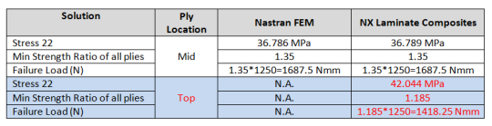
NXNASTRAN only outputs the mid-ply results for shell elements. From Table 1, it can be seen that when the bending loads are dominant, relying on the shell element mid-ply results is not conservative. NX Advanced Post Report is capable of calculating and extracting the ply results at Top and Bottom of the plies in order to achieve more accurate predictions. It also can be concluded that the effort required creating the geometry, 2D mesh, solve and post-process the results, was not necessary.