Quick Overview
This post-processing Tip & Trick will show how to calculate the stress margins of safety of a structure under a static pressure load, and then how to plot the margins and locate the critical areas of the part. This example, created in Femap 11.2, shows a solid mesh of a fan blade on which a pressure load was applied (Figure 1).
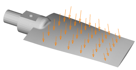
Figure 1
Steps
Once the NX Nastran analysis is complete and you have loaded or linked the stress results, you can generate an elemental envelope result based on the maximum nodal stress using Model->Output->Process->Envelope. After selecting the Von Mises solid stress (60031), be sure to include the nodal results (eg. SolidC1 VonMises) using the “Add Component/Corner Results” button (Figure 2)
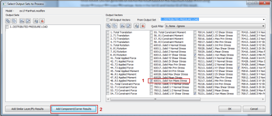
Figure 2
Then, you can use Model->Output->Calculate to compute % Margins of Safety based on the previous envelope result.
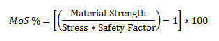
The margin of safety formula is:
The Femap dialog looks like this (Figure 3):
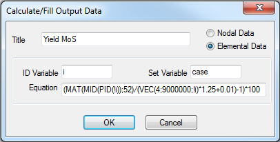
Figure 3
The equation is as follows:
(MAT(MID(PID(!i));52)/(VEC(4;9000000;!i)*1.25+0.01)-1)*100
Where
• Material strength is either the yield or ultimate strength of your material. Here it’s a query to get the tensile yield strength based on the element ID;
• Stress is the result of the envelope result previously generated. It can be recovered using the function VEC(SetID;VectorID;EntityID). Here it is VEC(4;9000000;!i);
• The safety factor is 1.25
The “+0.01” is to avoid division by zero for elements that may have no stress.
With the different Femap contour tools, you can then plot the stress margin of safety (Figure 4) and visually identify the critical stress area of your part.
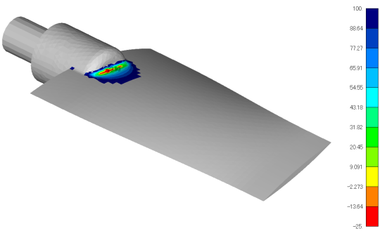
Figure 4
The margin of safety metric is perhaps more interesting when analyzing an assembly made of different materials, each having different yield or ultimate strengths.