Quick Overview
This Tips & Trick shows how to map Polygon Faces (i.e., CAE faces) to CAD Faces. Given a CAD Face in the Modeling application, what is its corresponding CAE Face in the Advanced Simulation application ?
Core content
How to find the corresponding CAE Face for a given CAD Face ? Visually, it is obvious to make the match in most cases. For example, Figure 1 shows three (3) faces of a cube in the Modeling application (in a PART file) and their corresponding CAE faces in the FEM part. Equivalent faces share the same color.
However, when writing a NXOpen script, the user does not see the geometry. Therefore, making the match between CAD Faces and CAE Faces is not straightforward. How can we proceed ?
The case of bodies
Matching bodies in NXOpen is easier that matching faces. Indeed, there exist Open C functions that provide the polygon body that corresponds to a given solid / sheet CAD body, and vice versa. These functions are:
1. int UF_SF_modl_body_ask_body (tag_t CAD_body, tag_p_t cae_body )
Input: the CAD body. It can be a solid or a sheet body.
Output: the CAE (polygon) body.
2. int UF_SF_body_ask_modl_body (tag_t CAE Body, tag_p_t CAD Body )
Input: the CAE (polygon) body. It can be a solid or a sheet body.
Ouput: the CAD body.
The first function takes as input the tag of the CAD Body and returns the tag of the corresponding CAE Body. The second function takes as input the tag of the CAE Body and returns the tag of the corresponding CAD Body.
Unfortunately, there are no such functions for CAD and CAE Faces. A different and less explicit approach should be used.
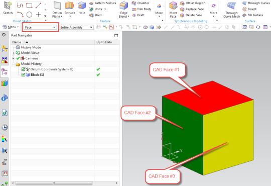
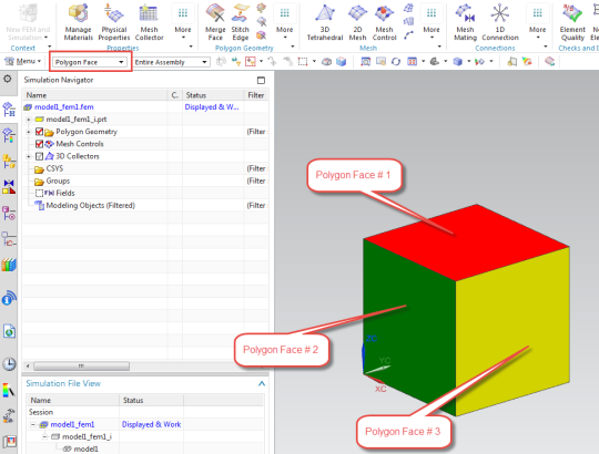
Figure 1: Three (3) CAD Faces of a cube (TOP figure) and their corresponding Polygon Faces (BOTTOM figure).
The power of attributes
Attributes of NX Objects are automatically transferred from PART to FEM (the inverse is not true !). For example, if an attribute is set to a CAD Face, the equivalent CAE Face will inherit the same attribute. To set manually an attribute in NX, right-click on the desired NX Object, go to “Properties“ and select the “Attributes” tab.
Figure 2 shows the attributes dialog of Face # 3. We have created a string attribute with the title “HELLO” and the value “FACE”.
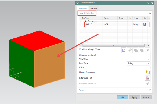
Figure 2: Setting an attribute for CAD Face # 3
Then we go to the FEM and open the attributes dialog for Polygon Face # 3. The polygon face inherits the attribute of its corresponding CAD face, as shown in Figure 3.
Mapping Polygon Faces to CAD Faces by using attributes.
After what has been discussed above, mapping between Polygon Faces and CAD Faces can be done using the following steps:
1. In the PART, loop over all CAD bodies using the Body Collection.
2. For each Body, get all the CAD Faces using the function GetFaces().
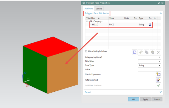
Figure 3: Attributes dialog for the Polygon Face # 3. The attributes are inherited from CAD Face # 3.
3. Loop over all the CAD Faces and for each, set a unique attribute using the function SetAttribute(). The attribute should be unique for each face. For example, set an attribute with title = “ID” and value = “FACE_1” for the first face and another attribute with title = “ID” and value = “FACE_2” for the second face.
4. Create a map that stores all the pairs (FACE, ID).
5. Go to the FEM.
6. Loop over all Polygon bodies using the function UF_SF_ask_all_polygon_bodies().
7. For each Polygon Body, get all the Polygon faces using the function UF_SF_body_ask_faces().
8. For each Polygon Face, read the attribute “ID” using the function GetUserAttribute().
9. Using the map created in step 4, find the corresponding CAD Face.