Quick Overview
This Tips & Trick shows how you can use the results from a coarse finite element simulation to assess potential delamination in a curved composite material.
The main steps are:
1. Extract the appropriate grid point forces or element forces that are applied to the bend;
2. Evaluate the interlaminar tensile stresses in the bend;
3. Evaluate the interlaminar shear stresses in the bend;
4. Compare the stresses to the material interlaminar strength values and obtain the overall margin of safety.
Core content
Starting from a coarse model, it is unlikely that the bend are modeled in a manner allowing the straight extraction of interlaminar stresses. Instead, it become necessary to extract the appropriate grid point forces and/or element forces (shell resultant) and use these values in a hand calculation.
Because this mode of failure is driven by the shear and tensile strength of the resin, it is customary to assume smeared laminate properties. With this, the modulus of elasticity of the laminate in the direction of the bend is assumed to be uniform across the thickness.
Interlaminar Tension
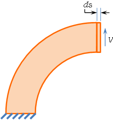
A curved laminate that is being pried open will typically exhibit delamination. This should not come as a surprise since the outer plies, following a larger radius than the inner ply must therefore be longer. Should the laminate be “unbent”, the length of the “flat” laminate will be driven by the shorter inner plies and the longer plies will therefore have a tendency to buckle and separate from the others in order to fit the shorter length.
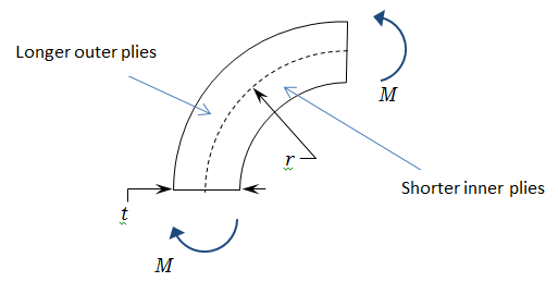
Of course, we are interested calculating the loads that can be applied to the bend before delamination occurs. For this, we will first derive the interlaminar tensile stresses as a function of the moment applied on the bend.
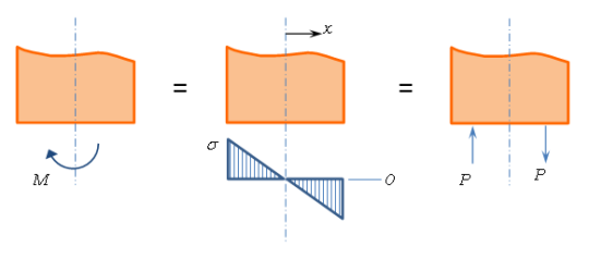
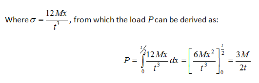
First, looking at each end of a unit length bend, the moment can be translated into stresses and loads as shown in the following illustration.
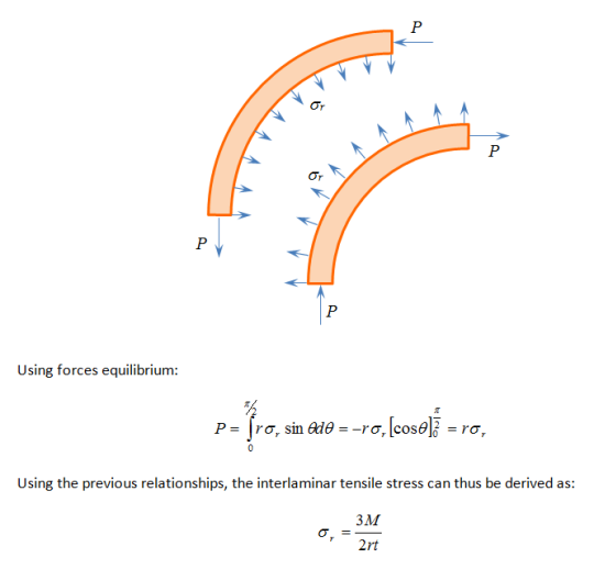
Splitting the laminate at the mid-plane, a free-body diagram can be drawn for each half of the laminate as shown in the following illustration:
Interlaminar Shear
In the previous section, we have seen how a moment applied to a laminated bend will result in interlaminar tensile stresses. If a shear load is applied to the end of the bend, interlaminar shear stresses will be generated as well.
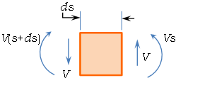
Looking at an element away from the shear load, we have the following free-body diagram:
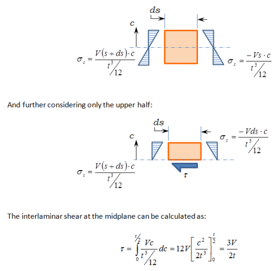
Considering the moments and converting them to stresses:
< b > Margin of Safety < /b>
Of course, once these stresses have been obtained, one can compare them to the interlaminar strength values to obtain the tensile and shear failure indices:
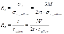
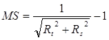
These stresses in the matrix can be expected to interact as they would in a standard composite material ply. It thus makes sense to use a quadratic interaction relationship. Using both failure indices, the margin of safety can thus be obtained with:
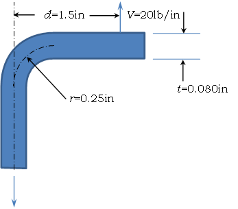
Example
Consider the following tension clip
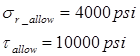
The material’s interlaminar strength values are given as:
The moment applied to the clip is obtained with:

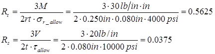
The failure indices can then be calculated as:
And the margin of safety is finally obtained:
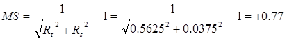
The bend is thus capable of handling this loading condition adequately.