Demo Video
Associative 3rd Party CAD Geometry
A common limitation when accessing CAD data from a CAE tool is the inability to support design changes with automated updates of the idealized CAE geometry, mesh, loads, and constraints.
The idealized CAE geometry must be responsive to changes to the CAD geometry; this is often referred to as associative (3rd Party) CAD. NX easily circumvents any limitations when working with native NX CAD, since the CAE geometry is fully associated with the CAD geometry via the idealized part. However, core functionality in NX also ensures that the CAE geometry and associated mesh, loads, and constraints will update with little or no user intervention when changes are made to 3rd party CAD geometry.
This function, called Wave Geometry Linker, is effective regardless of the source of the 3rd party CAD, and unlike some other CAE products, requires no special interface or software module. WAVE Geometry Linker enables associative 3rd party CAD, supporting design changes and avoiding simulation model re-work.
NX WAVE Geometry Linker
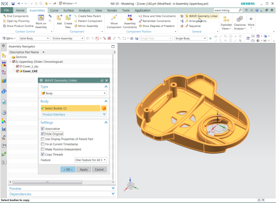
The WAVE Geometry Linker command in NX is used to copy geometry from one component in an assembly to another component. The geometry can be full bodies or subsets of bodies, for instance collections of faces or edges. When you replace the original component in the assembly, the associative linked component will update to match the new original component.
Work Flow
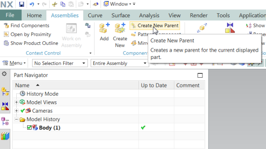
First make sure you are using an “advanced” role, then read in the 3rd party CAD data and create an upper level parent assembly. NX can read in virtually any mechanical CAD format, including both native formats such as CATIA and SolidWorks, and neutral formats like STEP and Parasolid.

Once the 3rd party CAD data has been read in, an upper level parent assembly is defined.
And then a new component (initially without geometry) is added to the assembly.
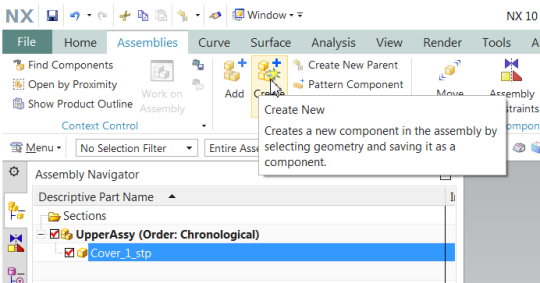
Making the new component the work part while leaving the assembly displayed (RMB the component in Assembly Navigator) we can now WAVE link the 3rd party CAD geometry into the new component.
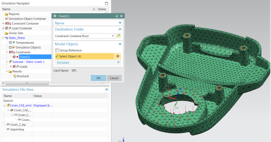
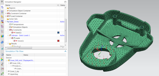
Make the new (WAVE linked) component displayed, and proceed normally. Idealize the geometry as needed, define material properties and mesh, apply loads and constraints, run and post-process the solution. The example shown here is for NX Nastran; however, the same work flow is valid for all supported solvers, including NX Thermal, NX Flow, and even 3rd party solvers such as Ansys and Abaqus.
Accommodating 3rd Party CAD Design Changes without Re-Work
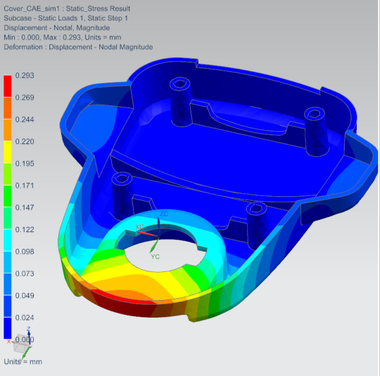
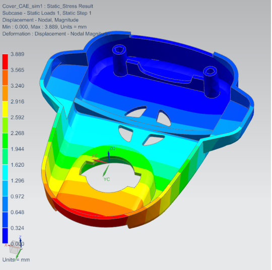
In this scenario you can see that the 4 mm deflection is unacceptable for the given clamping load. You have provided that input to the designer and suggested he include a second hold-down feature with two additional screw holes, in the vicinity of the stiffening web. Due to changes in design requirements during the interim, the designer has also eliminated the four concentric cut-outs in the middle of the cover. Open the new 3rd party CAD file
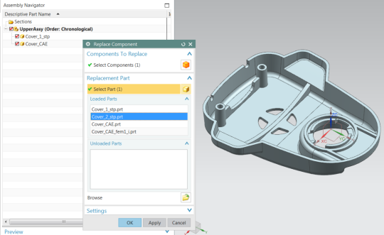
Make the upper level parent assembly the displayed part in the NX Modeling Application and replace the original 3rd party CAD component (RMB in Assembly Navigator) with the new 3rd party CAD. This has effectively broken the link; accept any warnings for now and we will repair the link.
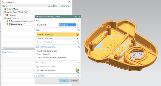
RMB the newer (WAVE linked) component in Assembly Navigator and make it the Work Part. Then RMB the Linked Body feature in Part Navigator and select Edit Parameters. Select the new body to repair the link and then click on Replacement Assistant.
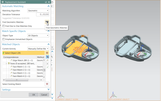
Replacement Assistant maps all faces, edges, and vertices from the original geometry to the new geometry, so that all downstream processes including idealization, meshing, loads, and constraints are maintained. Replacement assistant will even accommodate both removal and addition of geometric features; we’ve done both here. Make sure Matching Algorithm is set to Geometric and select Find Geometric Matches.
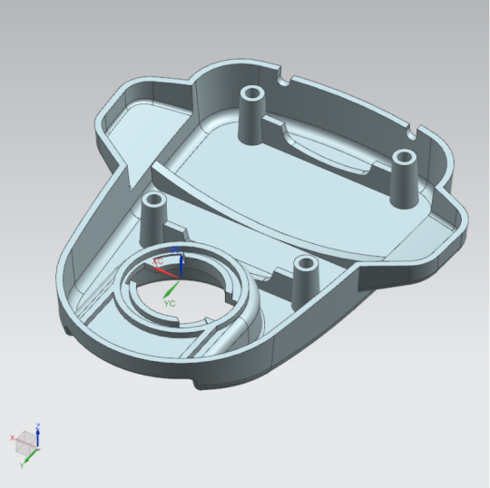
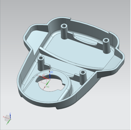
Now toggle to the idealized part and note that the cutout is gone, the new boss feature is present, and all idealization work is maintained.
Toggle to the fem and update the mesh; finally toggle to the sim and note that the constraints and loads have been maintained. It’s now a simple matter to add the two additional screw holes to the fixed constraint and re-run the solution. Displacement has been reduced to a fraction of its previous level.